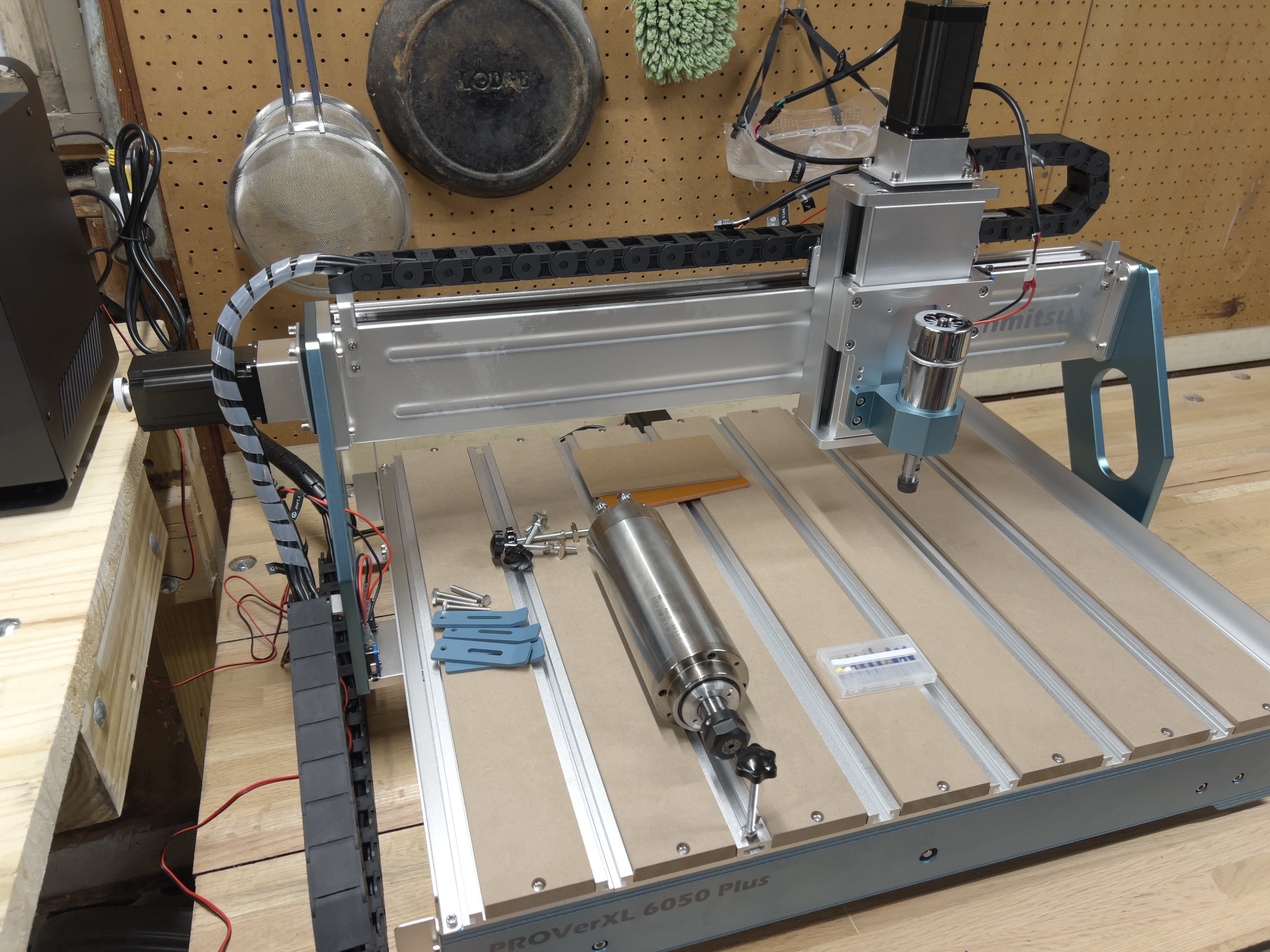
I needed to manufacture metal parts with reasonable precision. After months of research I bought a Genmitsu 6050 router with the intention of modifying it for milling metal.
A manual mill was an option, but CNC removes a lot of human error and makes complex geometry realistic. On a limited budget, the plan was simple: start with a mostly functional machine and improve it as I learned both the router and milling itself.
Stock Genmitsu 6050: basic GRBL over USB, three open-loop NEMA 23 steppers, lead screws (~10–12 mm), usable work area about 600 × 500 mm with ~150 mm of Z. Main axes used HGR15–HGR20-class rails; Z still used linear rods. Stock spindle was a 300 W ER15 unit — fine for wood, plastics, and light engraving, not serious aluminum.
Most of the real learning happened as small projects stacked on top of each other. This is roughly the order I did them.
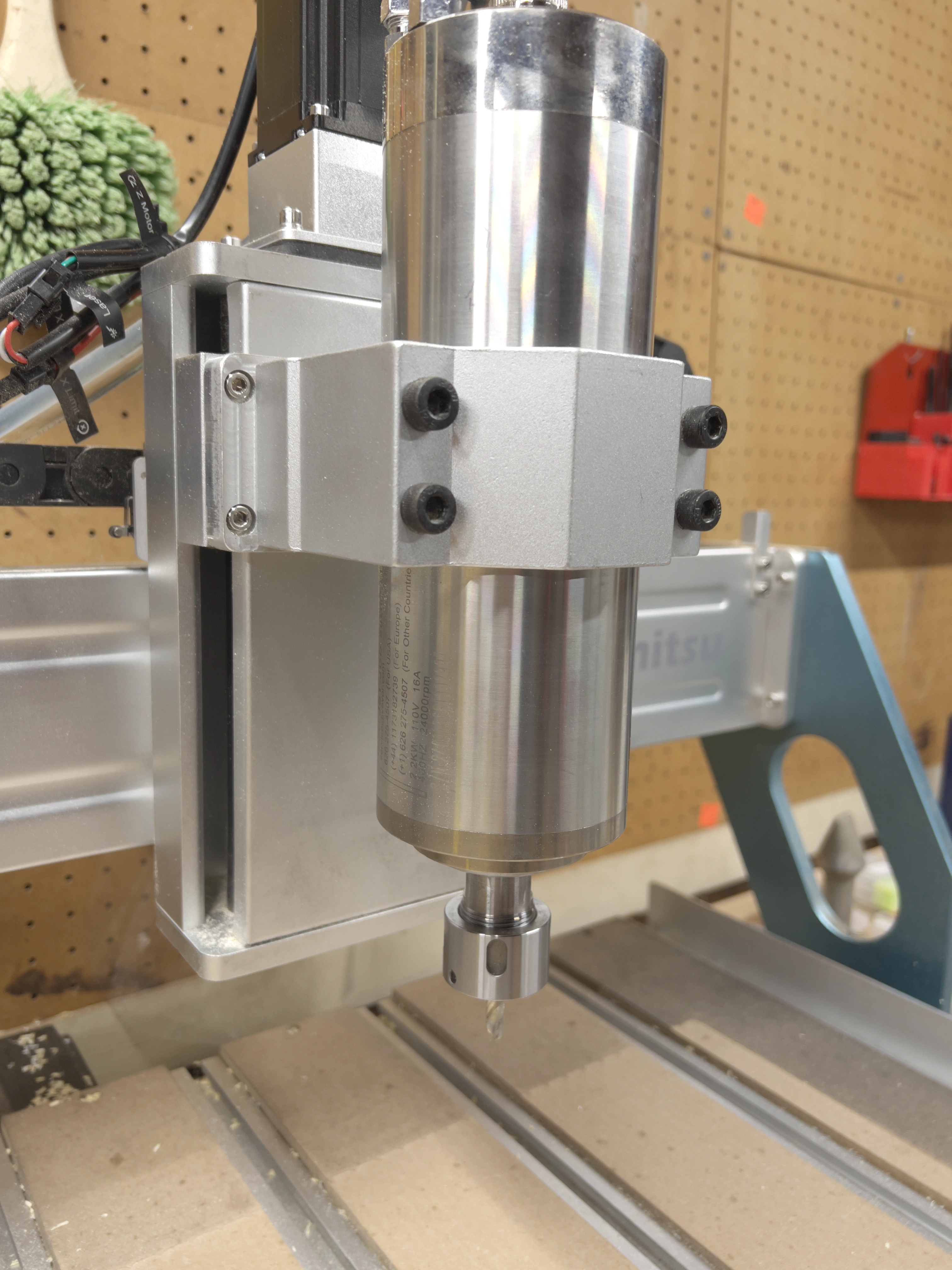
First change after buying the machine. The larger liquid-cooled ER25 spindle handles higher cutting loads, denser materials (aluminum and steel as real cuts, not just engraving), larger tools, higher RPM (up to ~20,000 vs ~10,000 on the stock unit), better concentricity / less runout, and runs quieter and cooler than the air-cooled 300 W spindle.
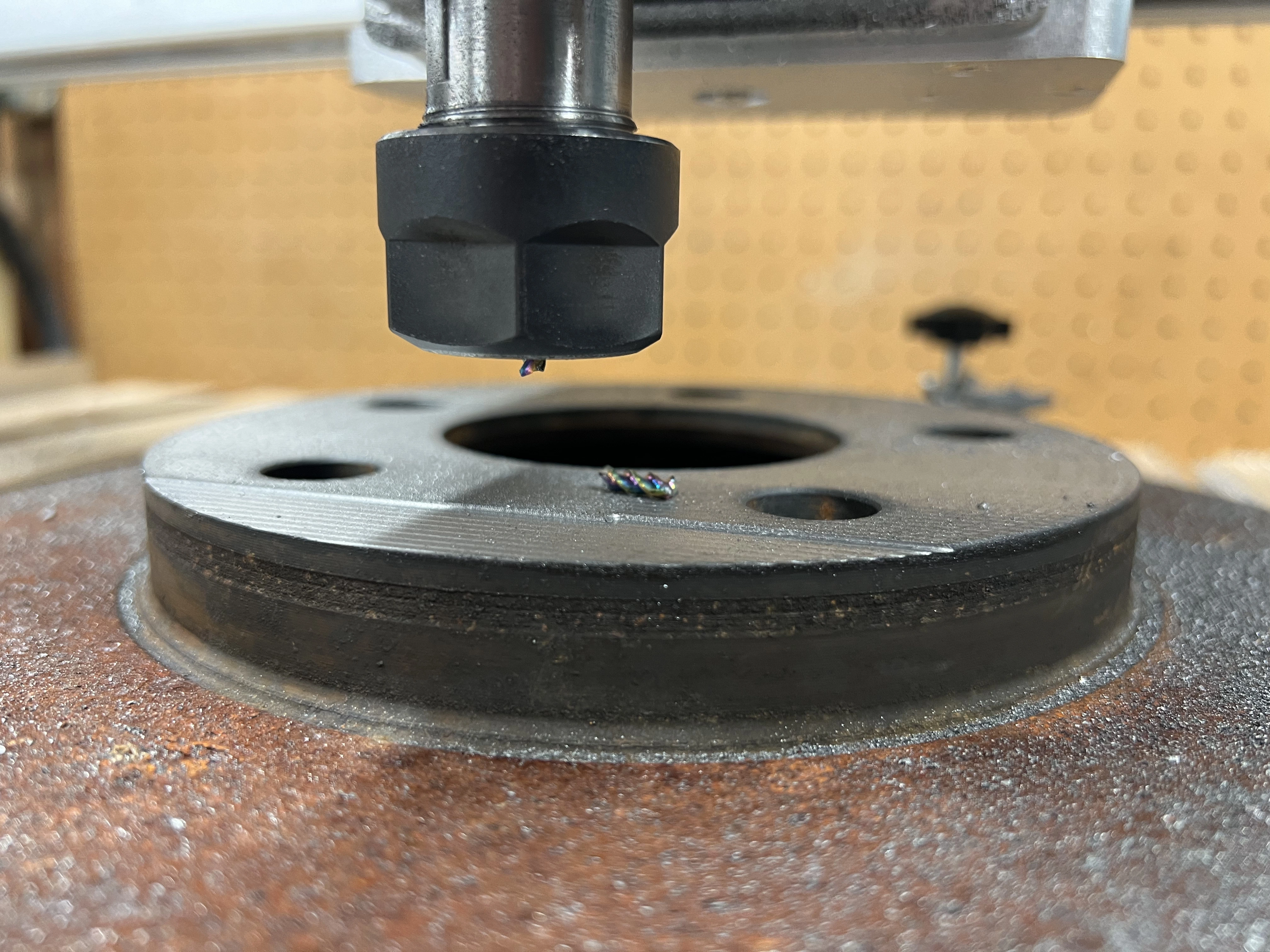
I jumped straight to aluminum and then steels and cast iron. Compared to the smaller router I had used before, this was a clear step up. On an old automotive brake rotor I could cut steel — only about 0.25 mm deep and ~3.175 mm (1/8 in) wide with a 3-flute endmill — until the tool hit hardened regions near the mounting points and snapped. Still, it proved steel was on the table.
Early hold-downs forced me into large stock, outline cuts, and tabs. That limited part shapes, wasted material, and was not very rigid.
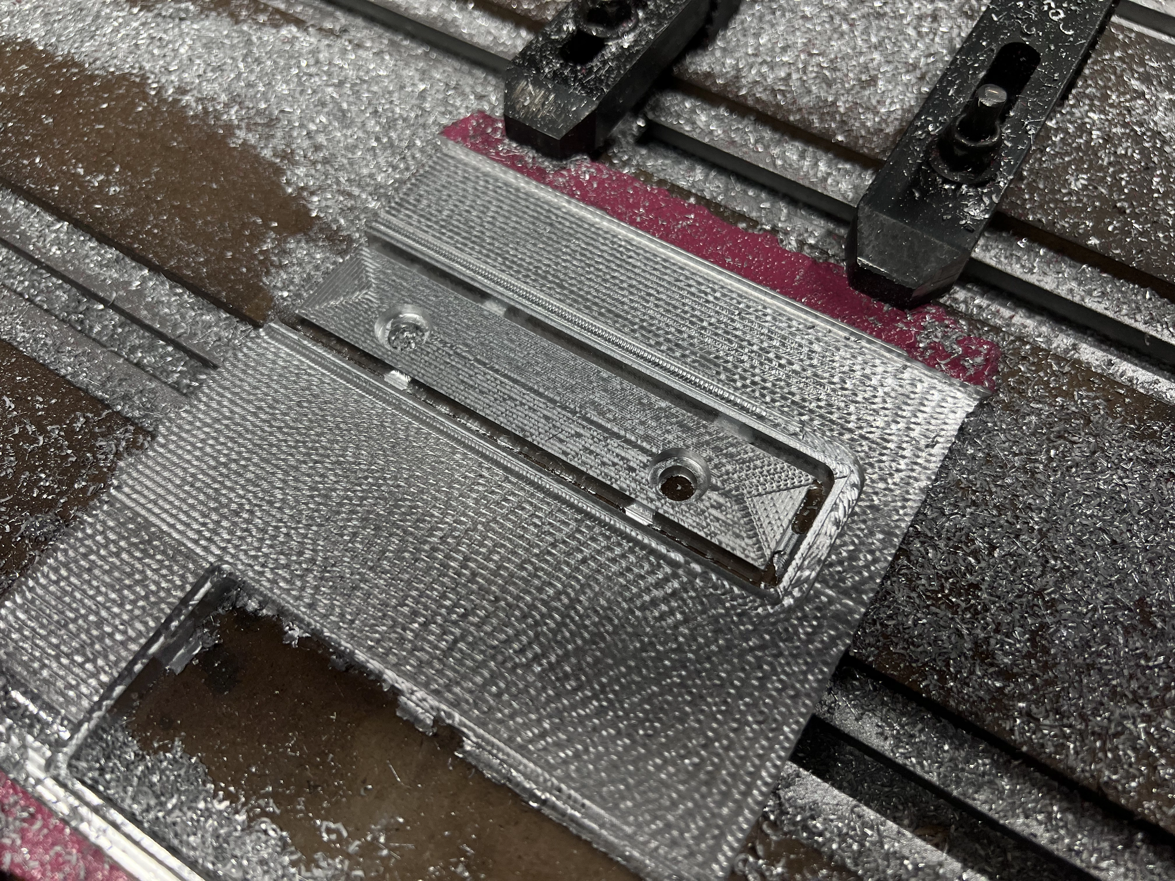
I bought a vise that “technically” fit the bed but was too tall — the gantry almost hit it and usable Z disappeared. That was the first hard limit of this machine: gantry clearance.
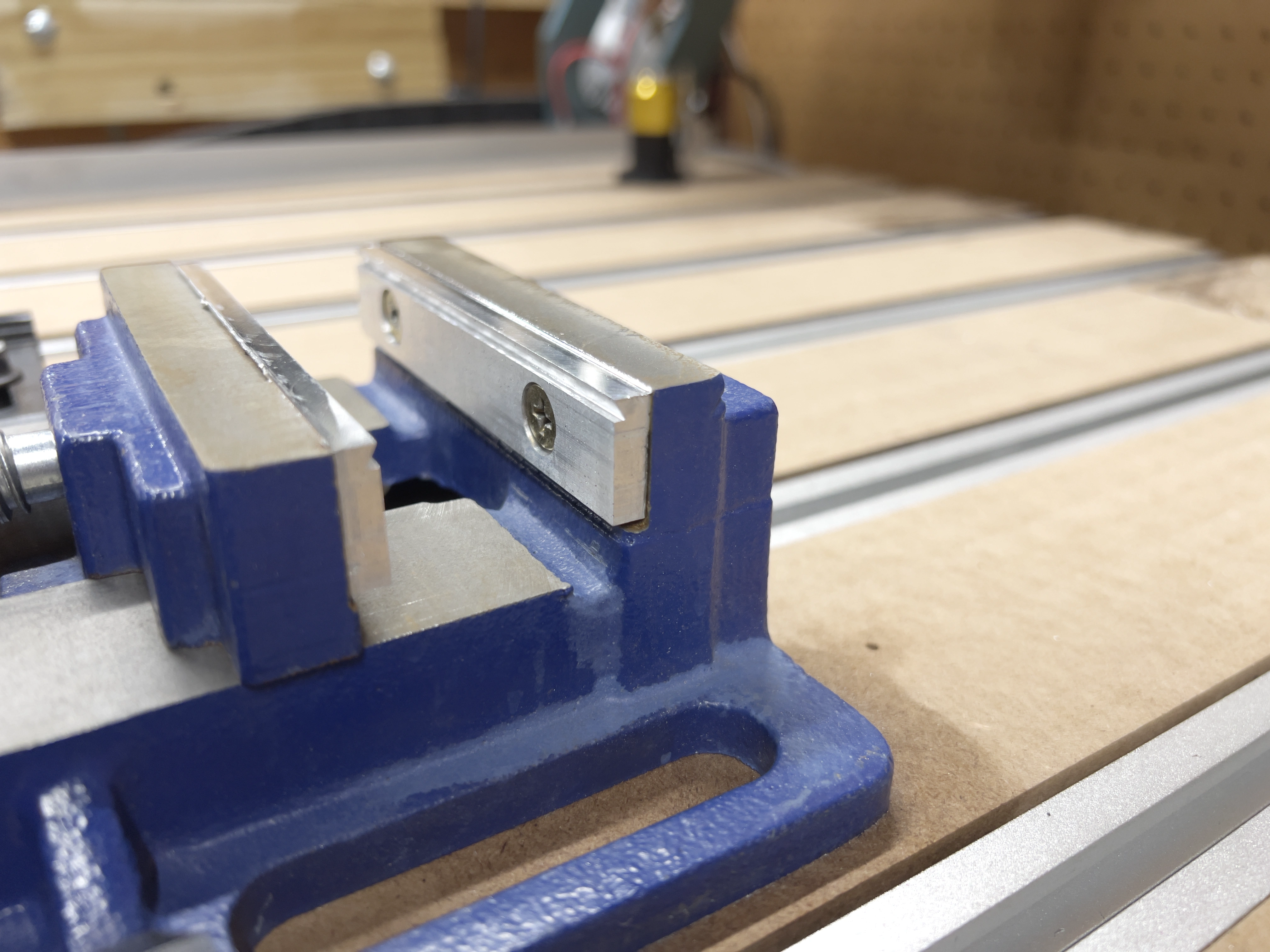
A low-profile cast vise fixed the height problem, but it rocked on the table. I trued the contact so the vise sat flat and the stock stayed square. Then jaw lift showed up — several millimeters under clamp. I made a tighter aluminum “jaw clamp” to replace the loose steel plate under the jaw. Aluminum wears instead of chewing the steel ways; jaw lift dropped to under 0.1 mm under normal force.
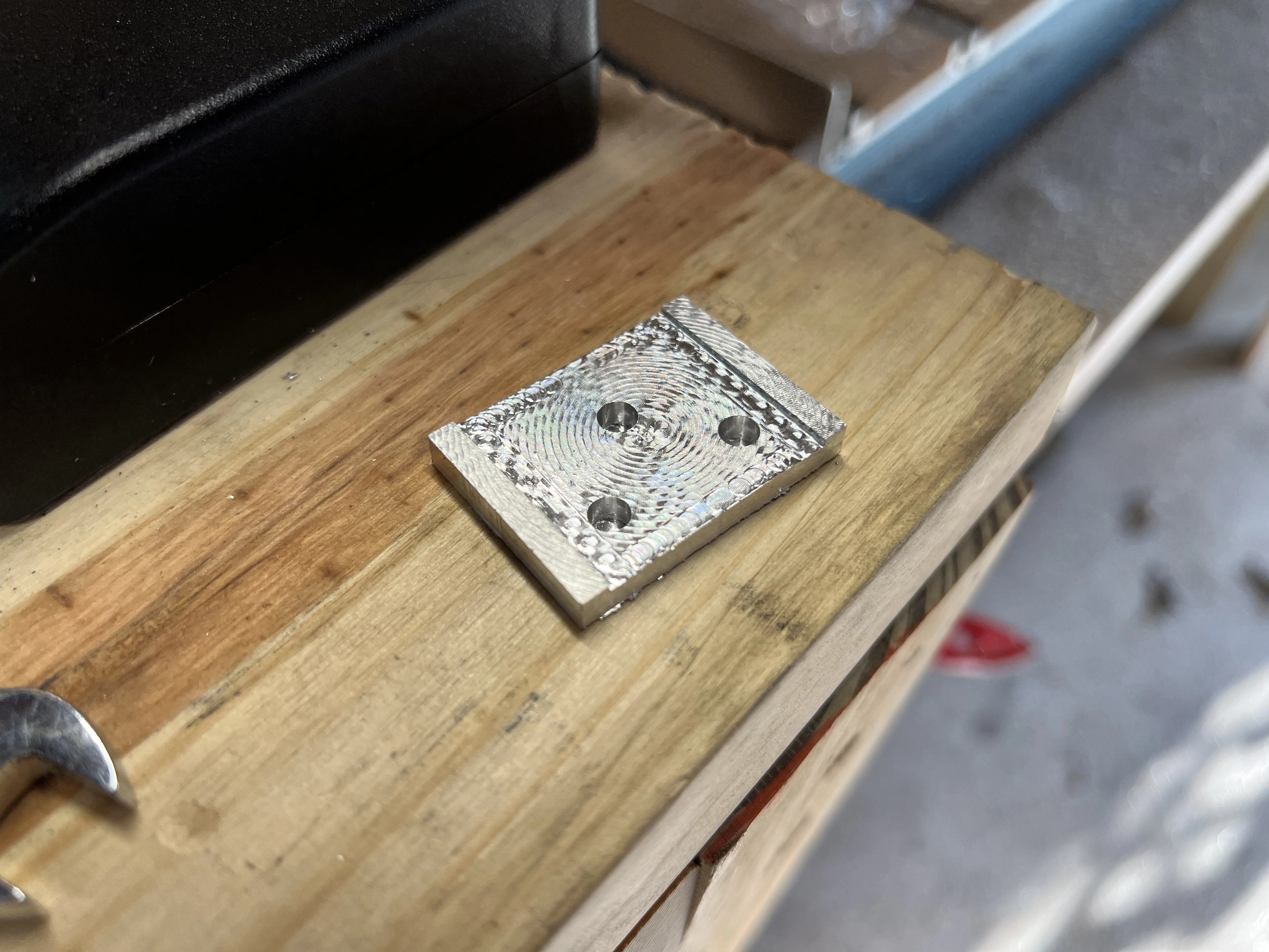
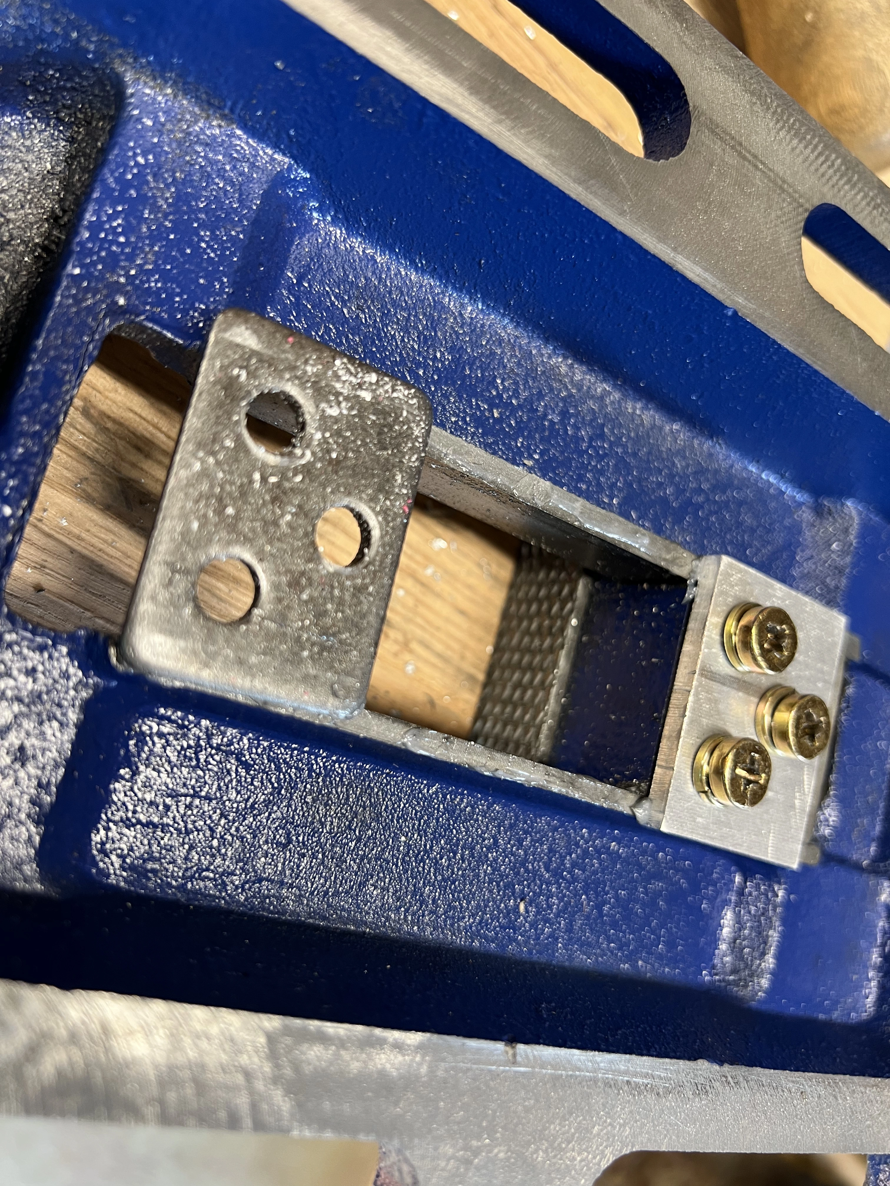
I was melting scrap aluminum into triangular ingots and needed flat plate for the router. Wooden patterns and sand molds got me there. Volume was the limit — hard to pour large plates — but the biggest plate I managed became a desk paper holder.
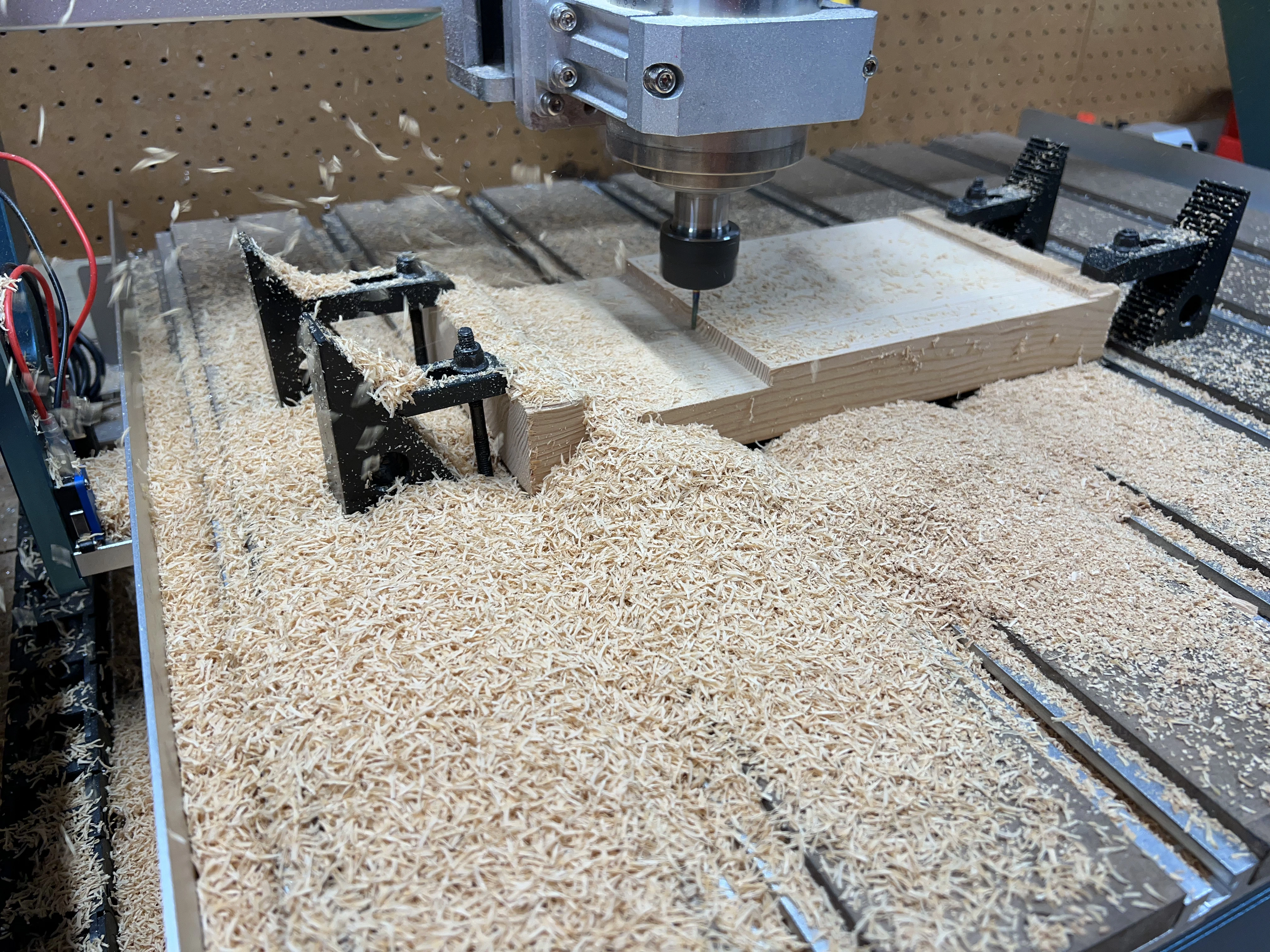
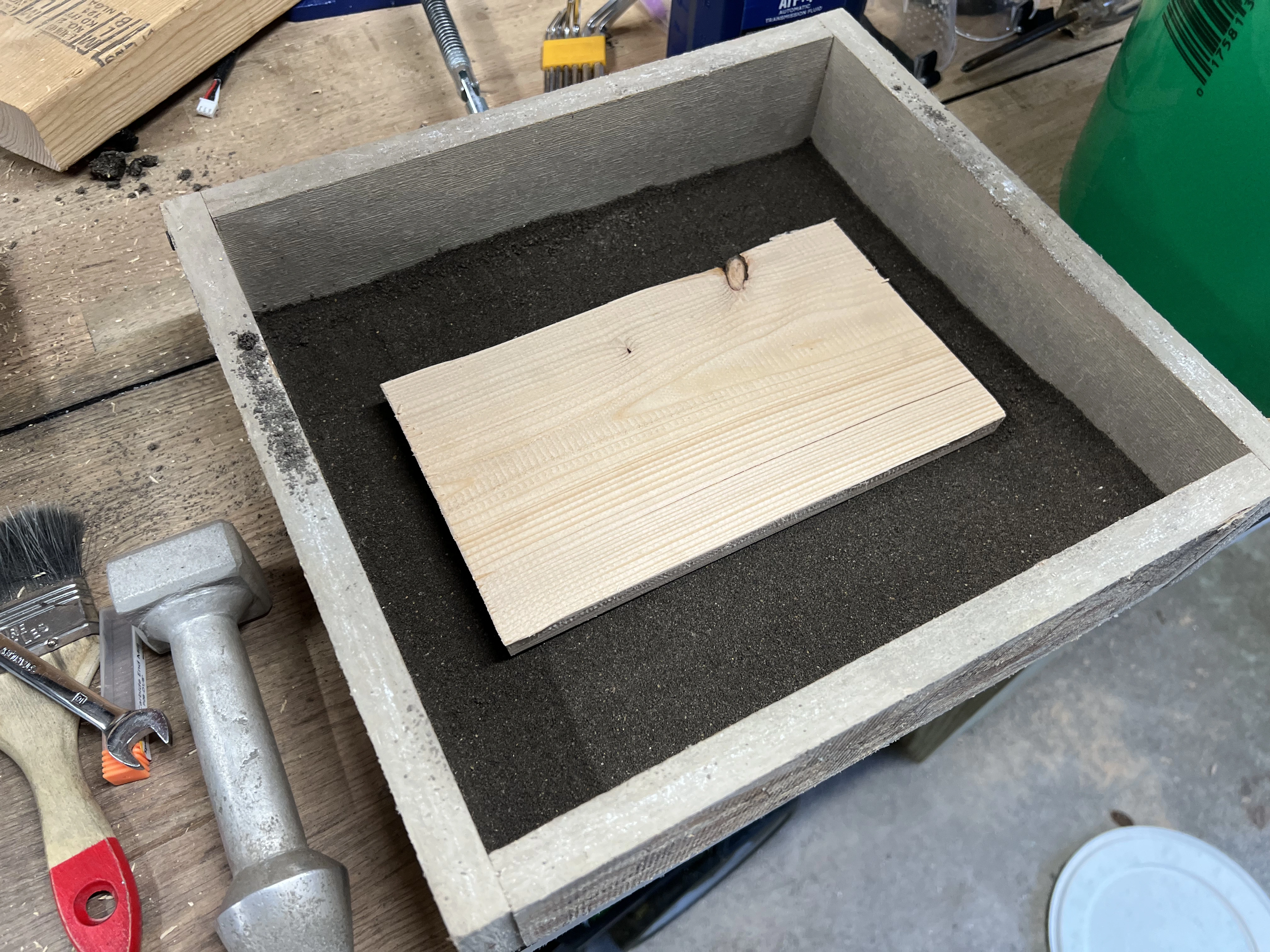
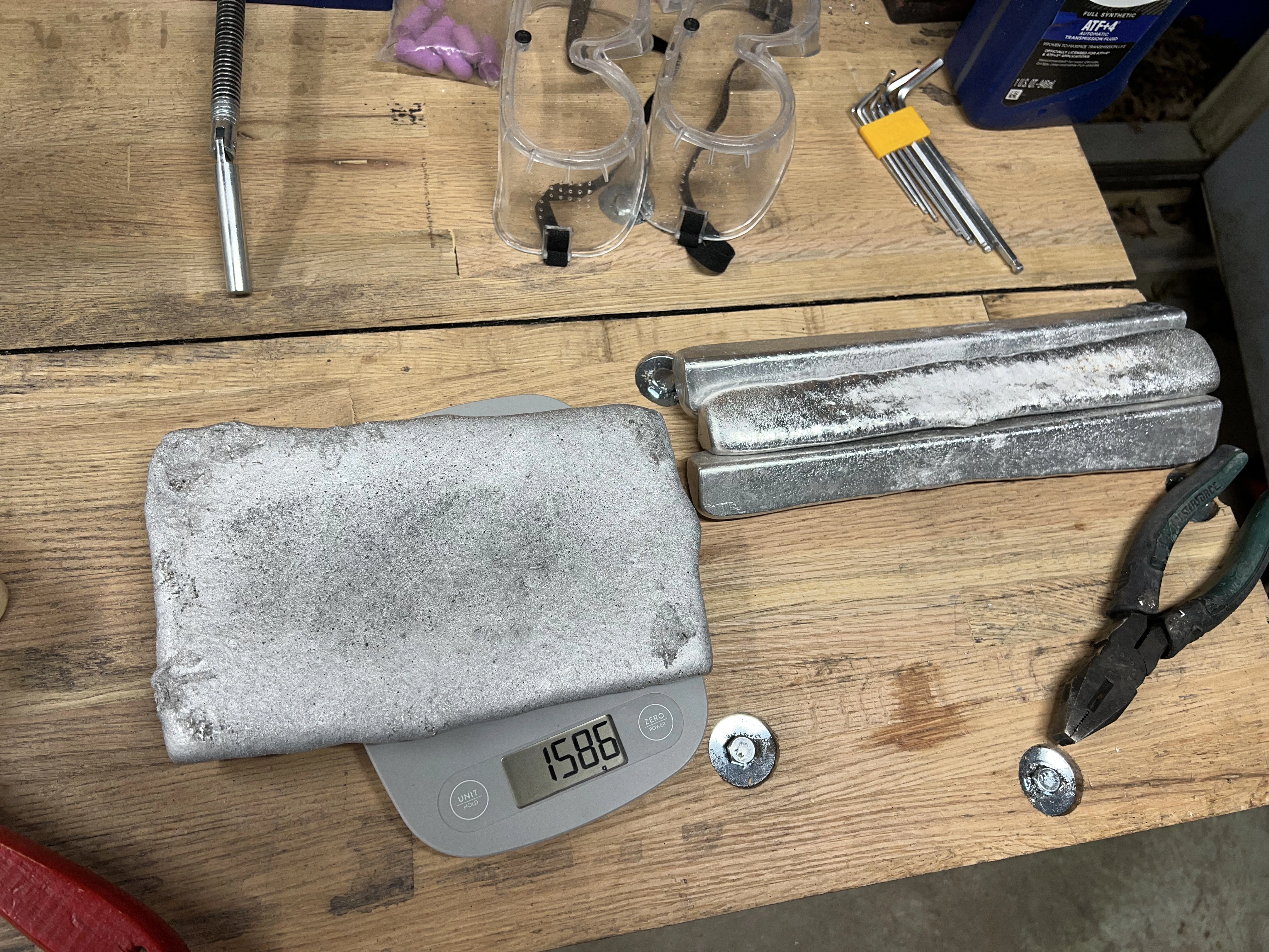
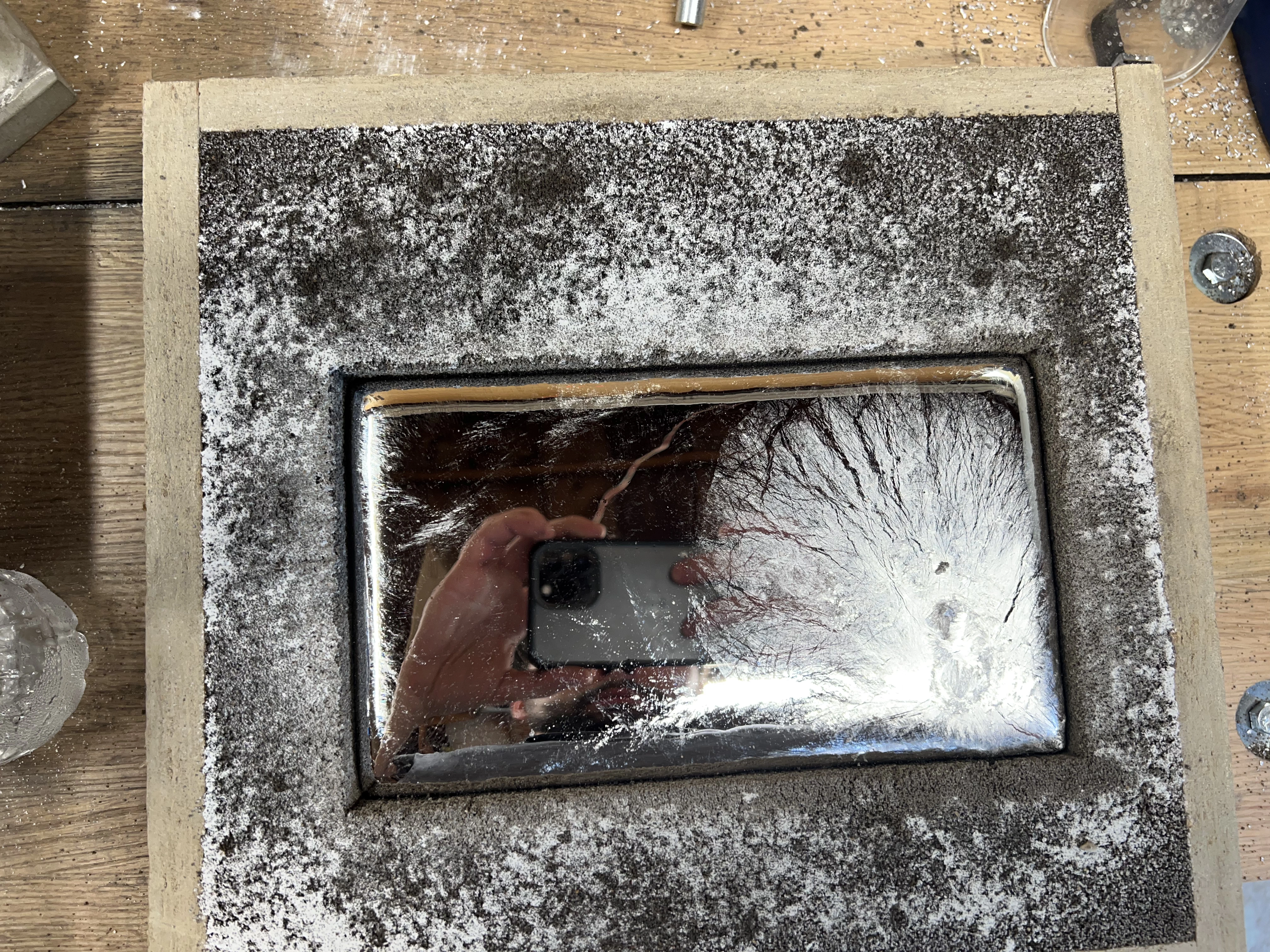
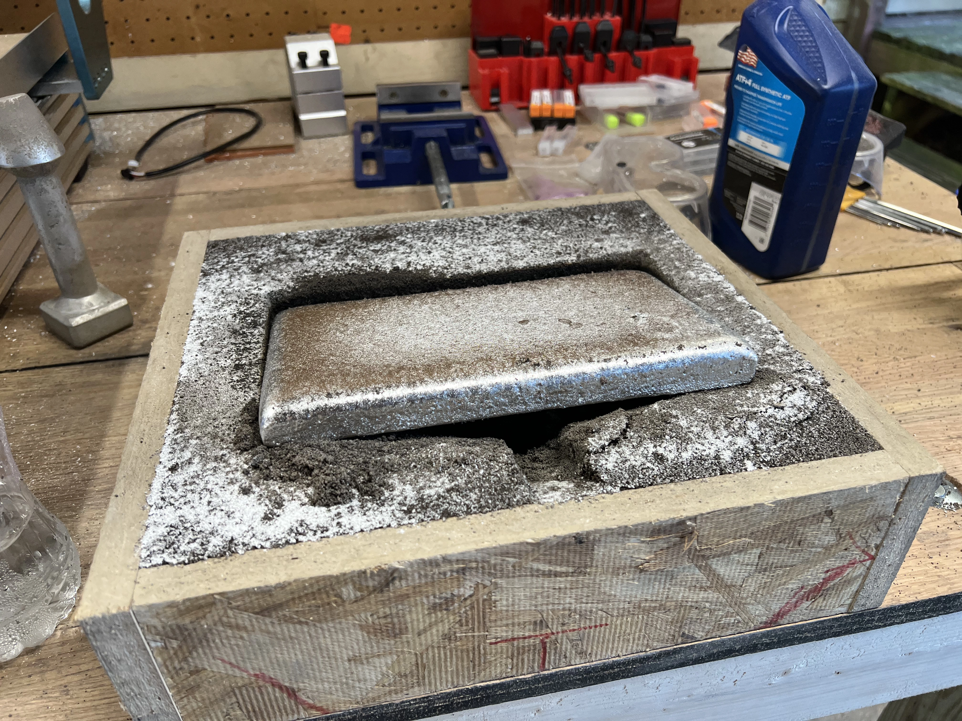
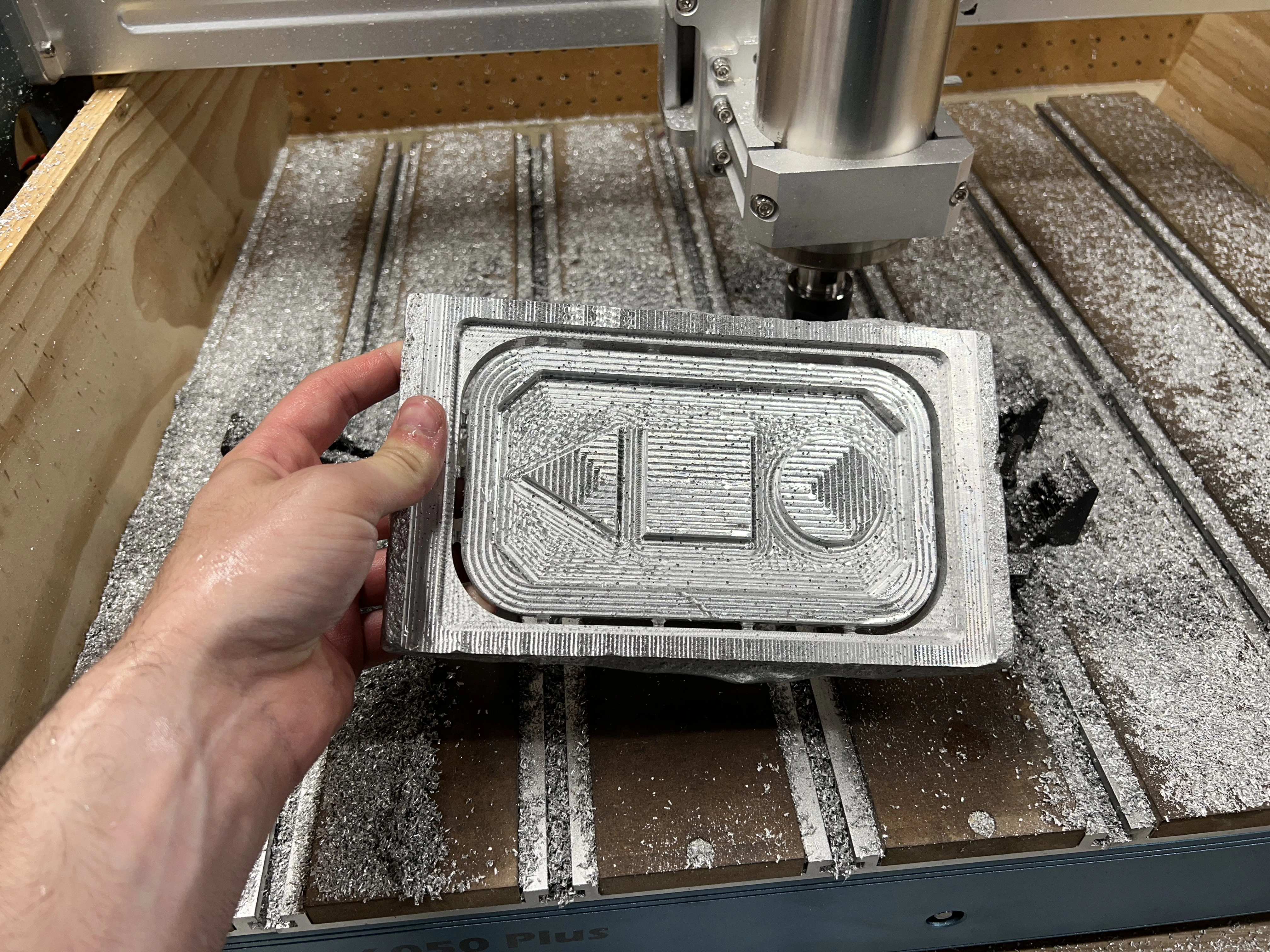
Early pours were porous. The melt had sat too long and picked up moisture from the air. Fix: get it hot and pour quickly. Covering fluxes help too, but that is its own project.
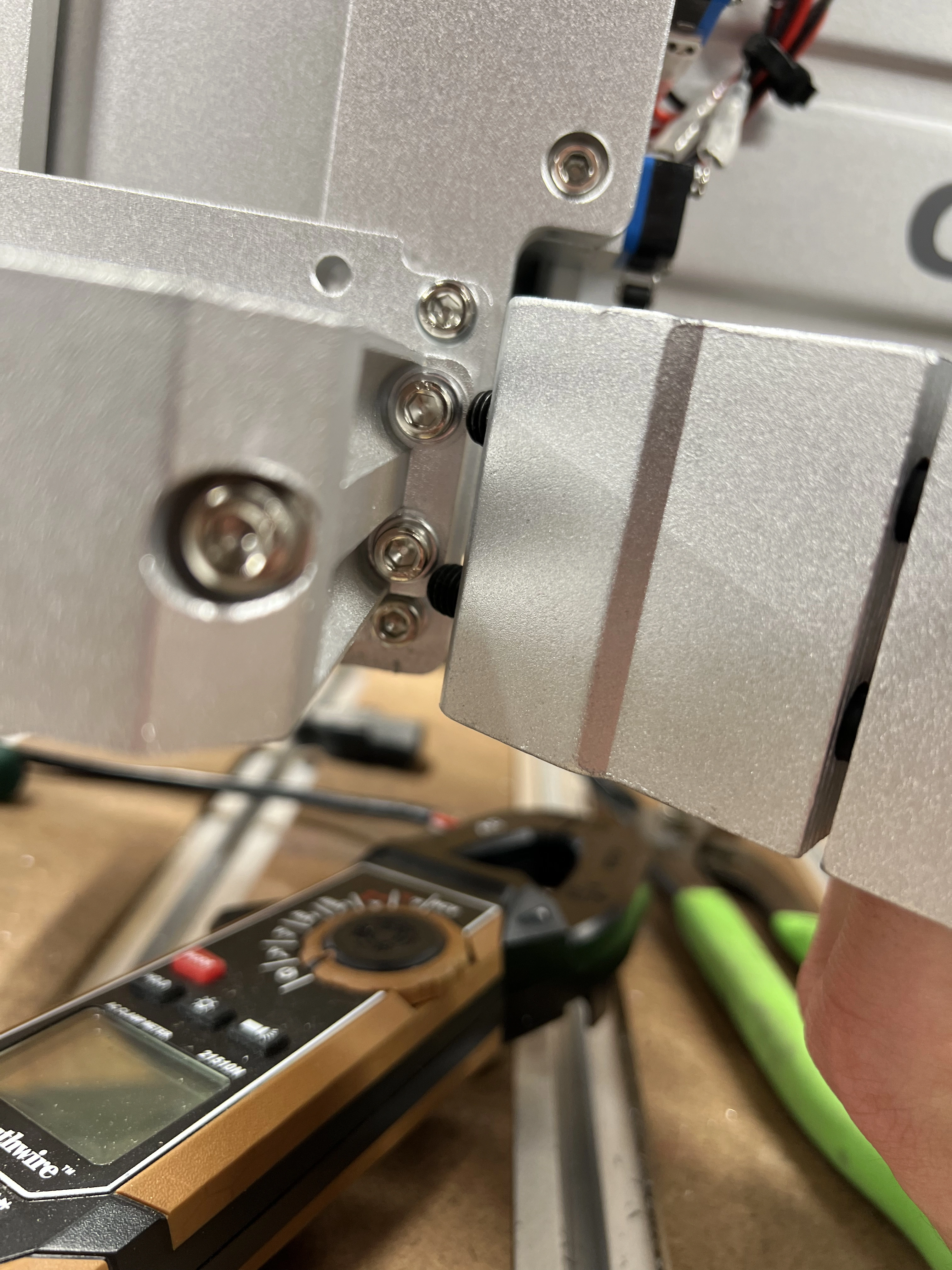
Same casting + machining workflow produced an adapter plate so I could use the larger spindle holder that came with the 2.2 kW spindle instead of the small Genmitsu adapter. That was one of the rigidity steps measured later at the tool tip.
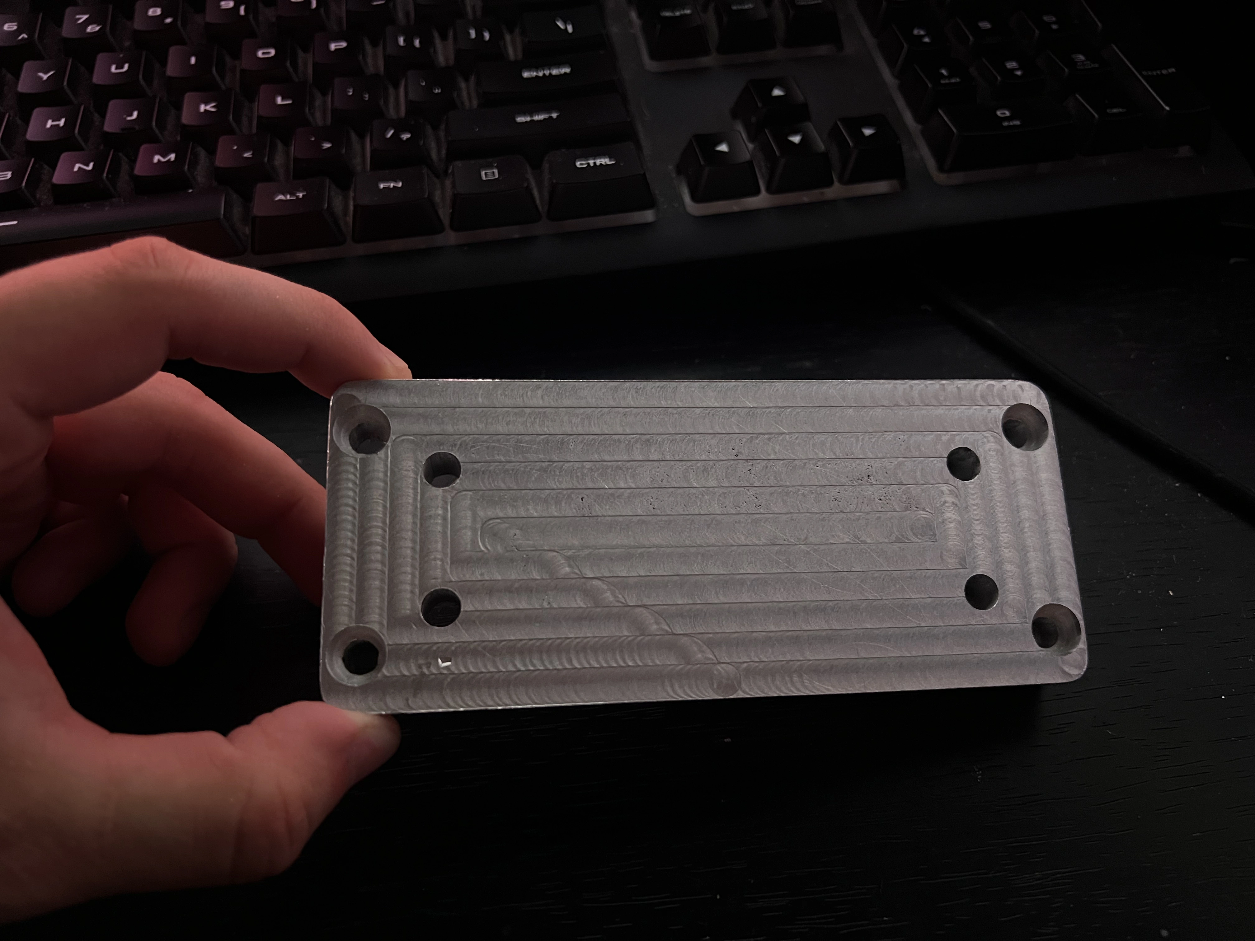
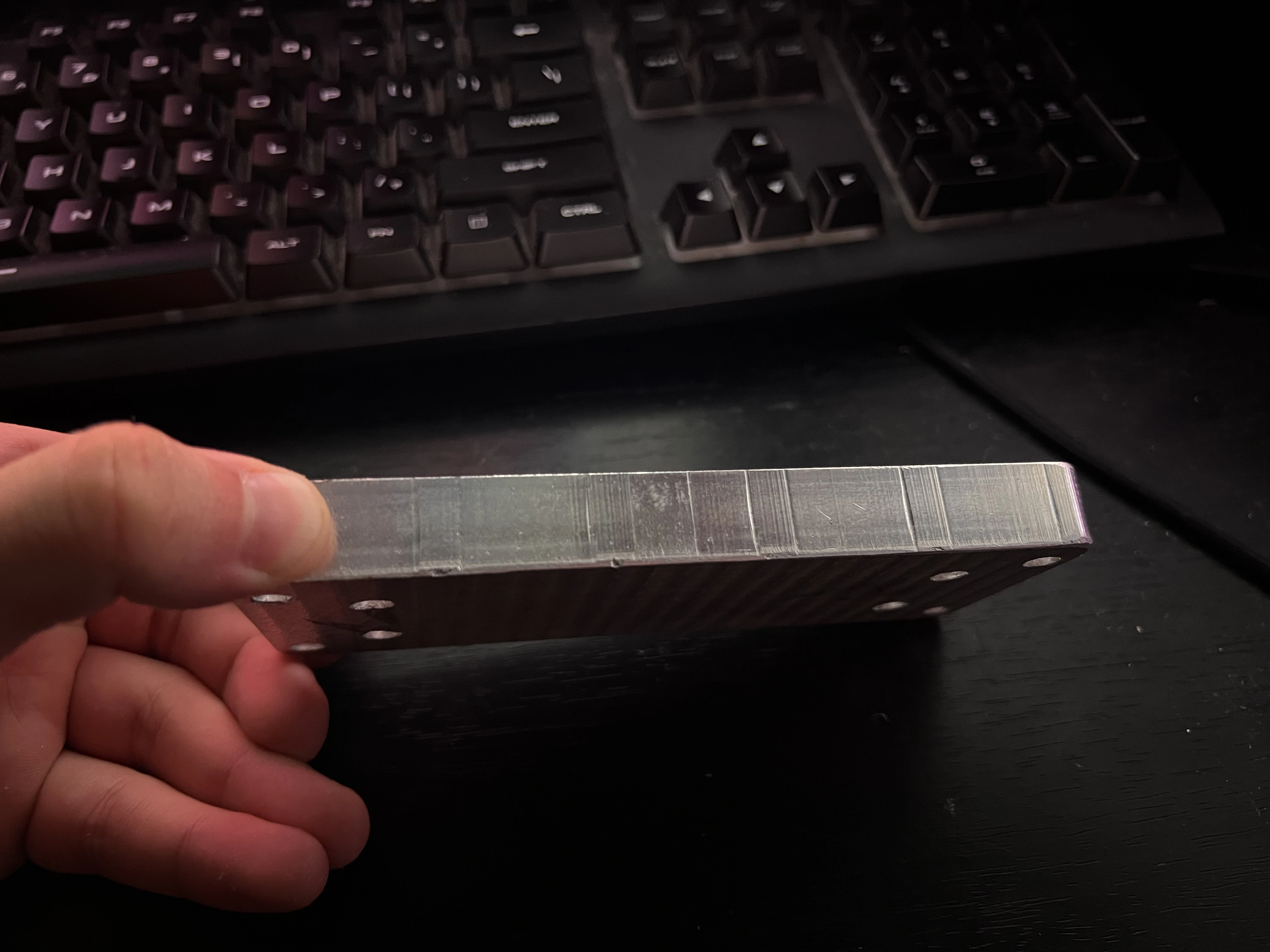
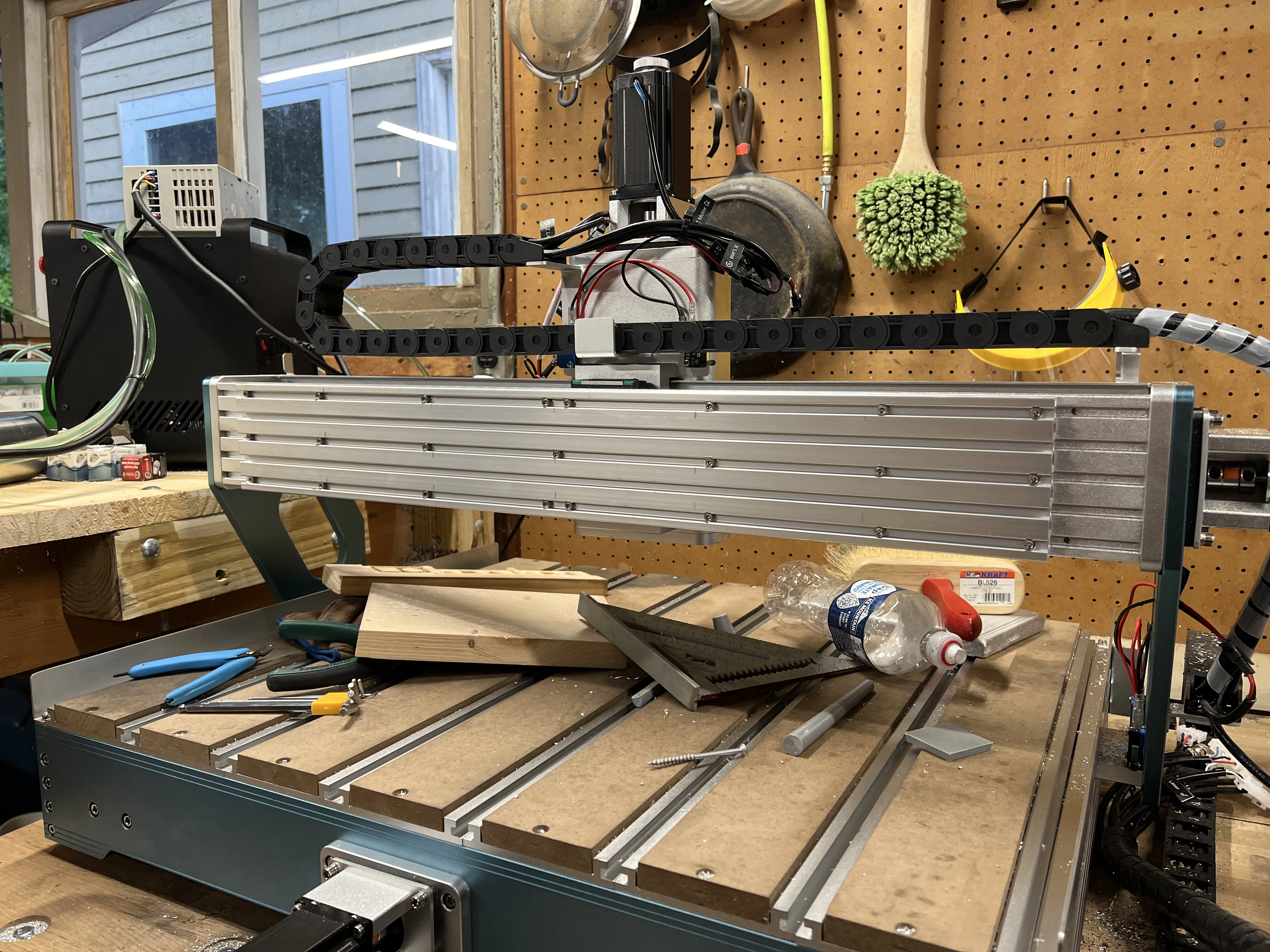
With the bigger spindle, aluminum loads bent the gantry and caused chatter. Bolting 80/20 extrusion to the back of the gantry plate cut tool-tip deflection roughly in half as part of the overall flex stack (stock >10 mm → ~5 mm after the brace → ~2–3 mm after the rigid spindle mount, under ~20 lb at the tool tip).
Held in the vise and cut as a real part for the axial-flux motor. Came out clean and was one of the first “this is why the mill exists” wins.
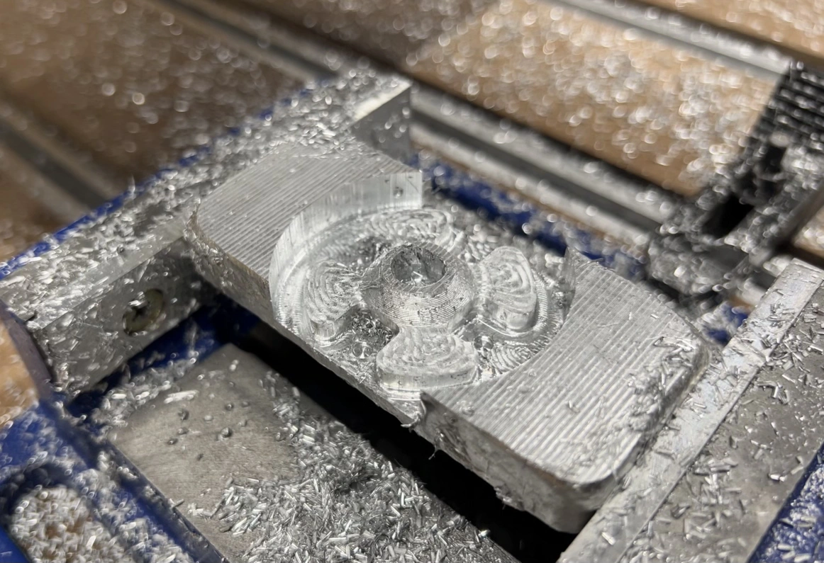
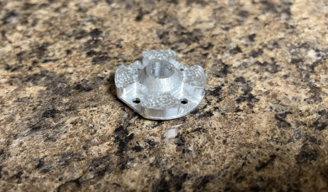
Until then I had mostly used 1/8 in tools. Tool stiffness scales hard with diameter: bending rigidity goes up with diameter to the fourth power, so doubling diameter is about 16× stiffer for the same stick-out and load. Deeper and wider cuts became realistic; usable aluminum DOC moved from roughly 2 mm before the rigidity work to around 8 mm afterward, with a stepover near half the tool width.
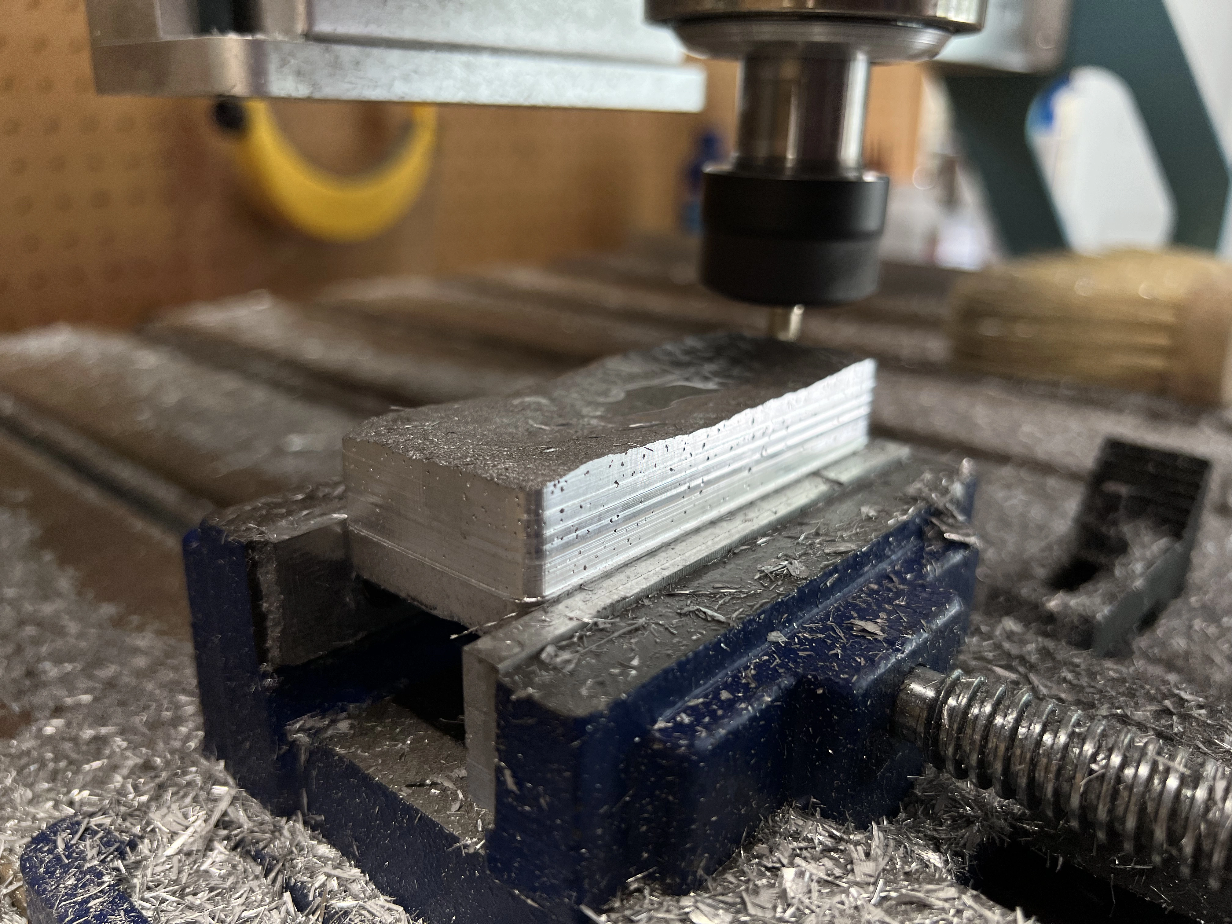
Metric thread-mill kit plus published formulas for parameters. Got consistent threads — a process I expect to use constantly on motor and machine parts.
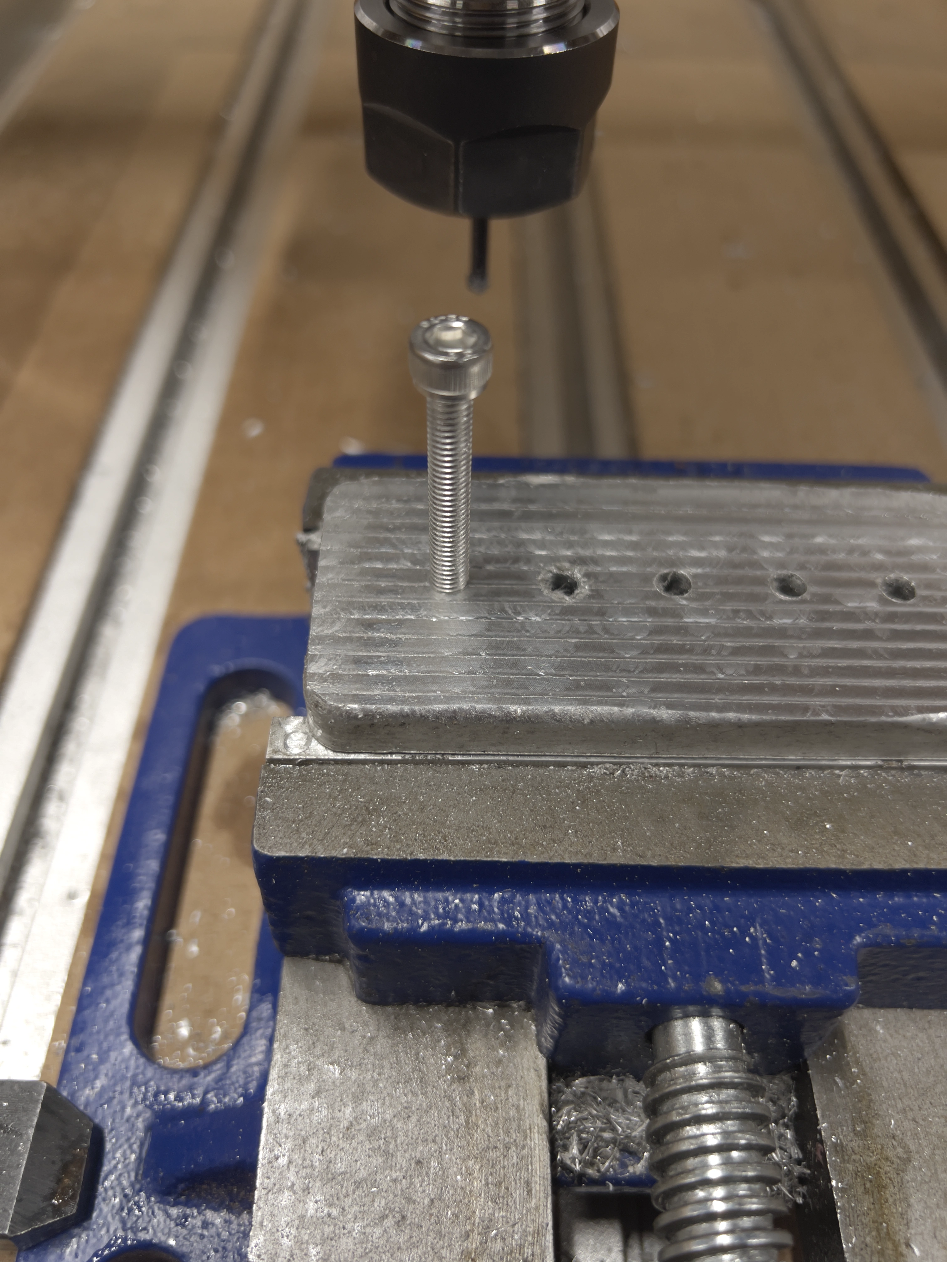
For Purdue’s IEEE (Institute of Electrical and Electronics Engineers) go-kart club I machined a battery module cover from club-supplied stock in the vise. At that point dimensional accuracy was about 0.2 mm on Z and better than0.05 mm on X/Y. X/Y was acceptable for lead screws and open-loop steppers; Z was the weak axis — flex plus manual zeroing after tool changes.
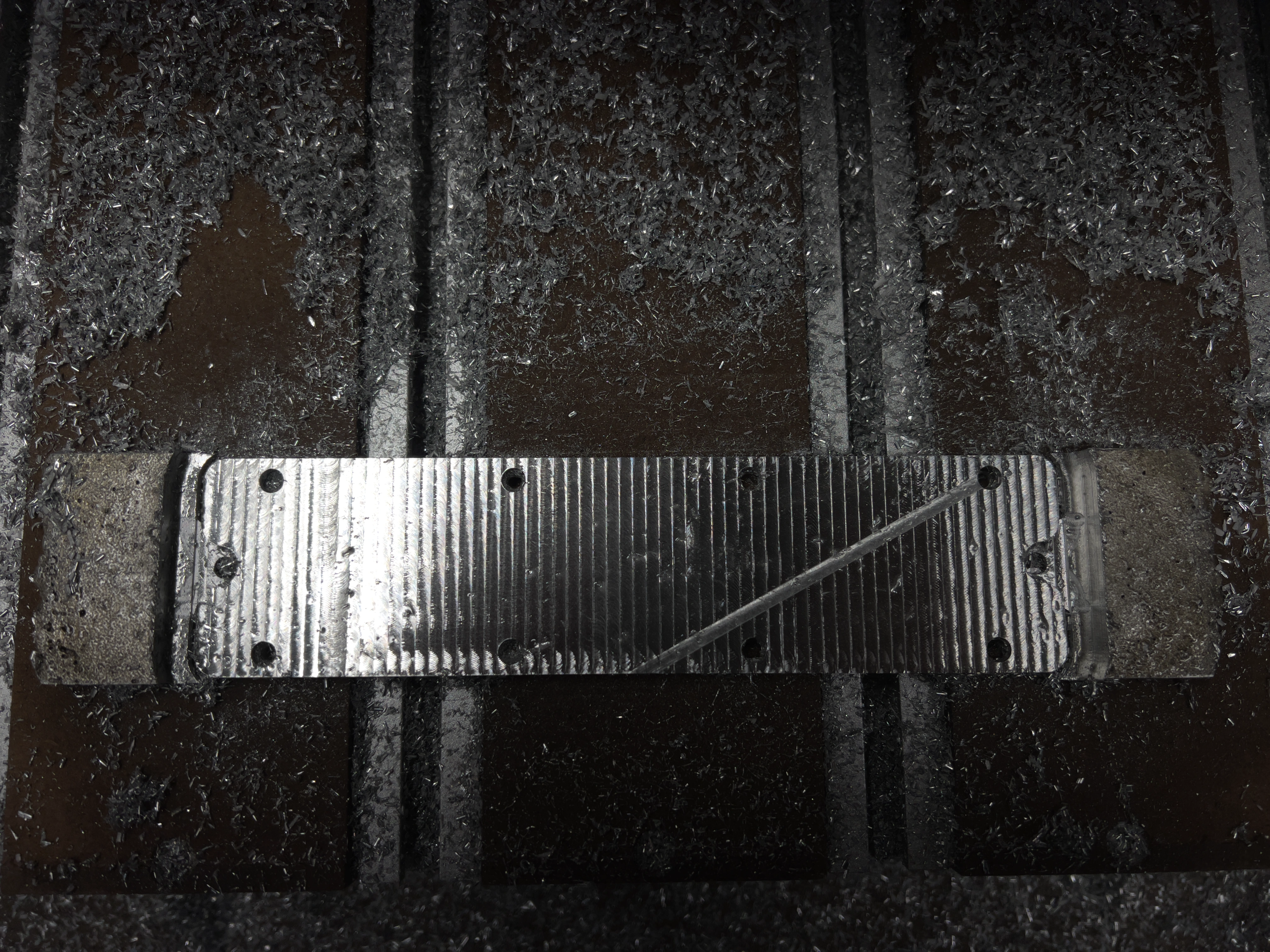
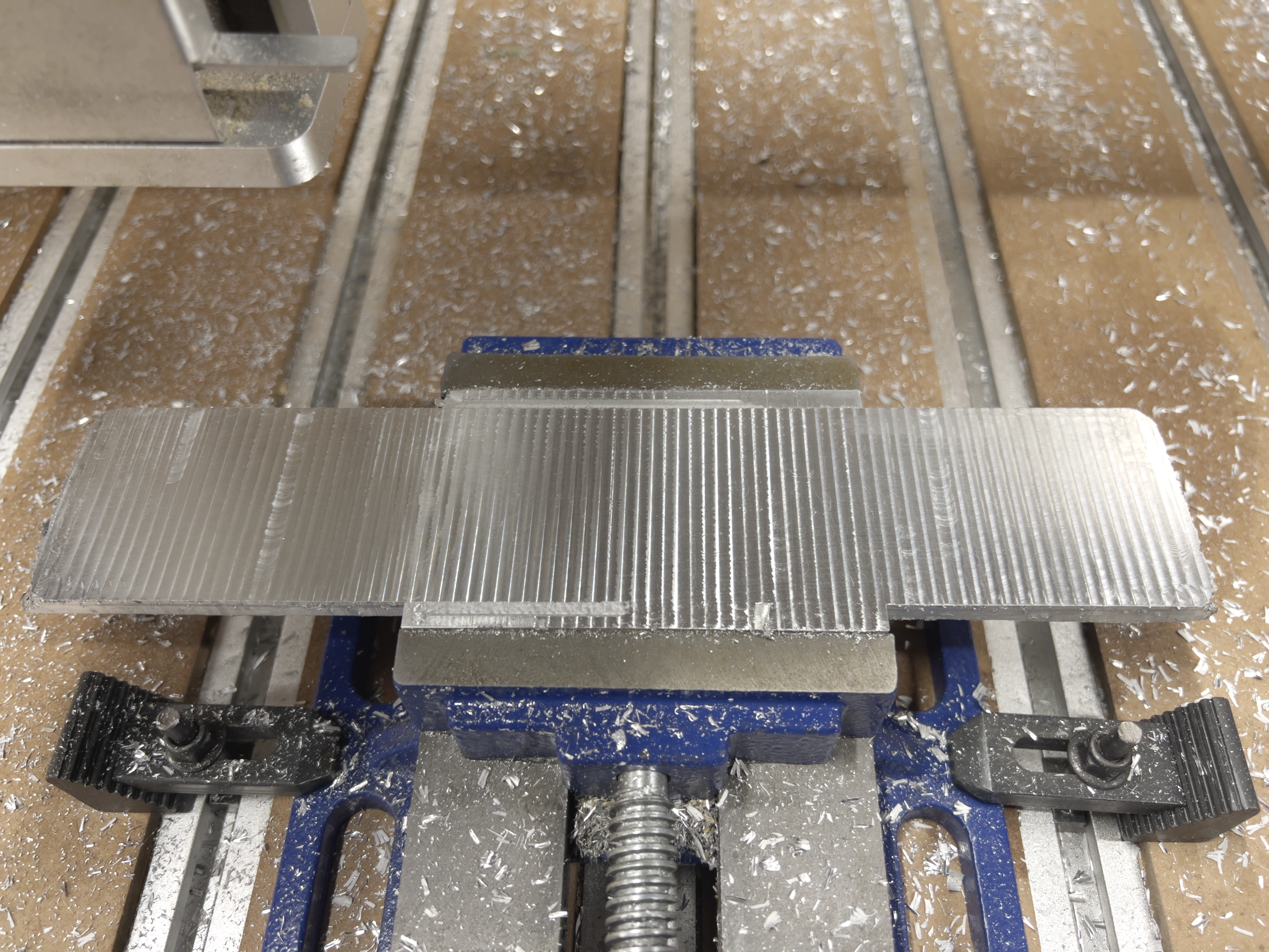
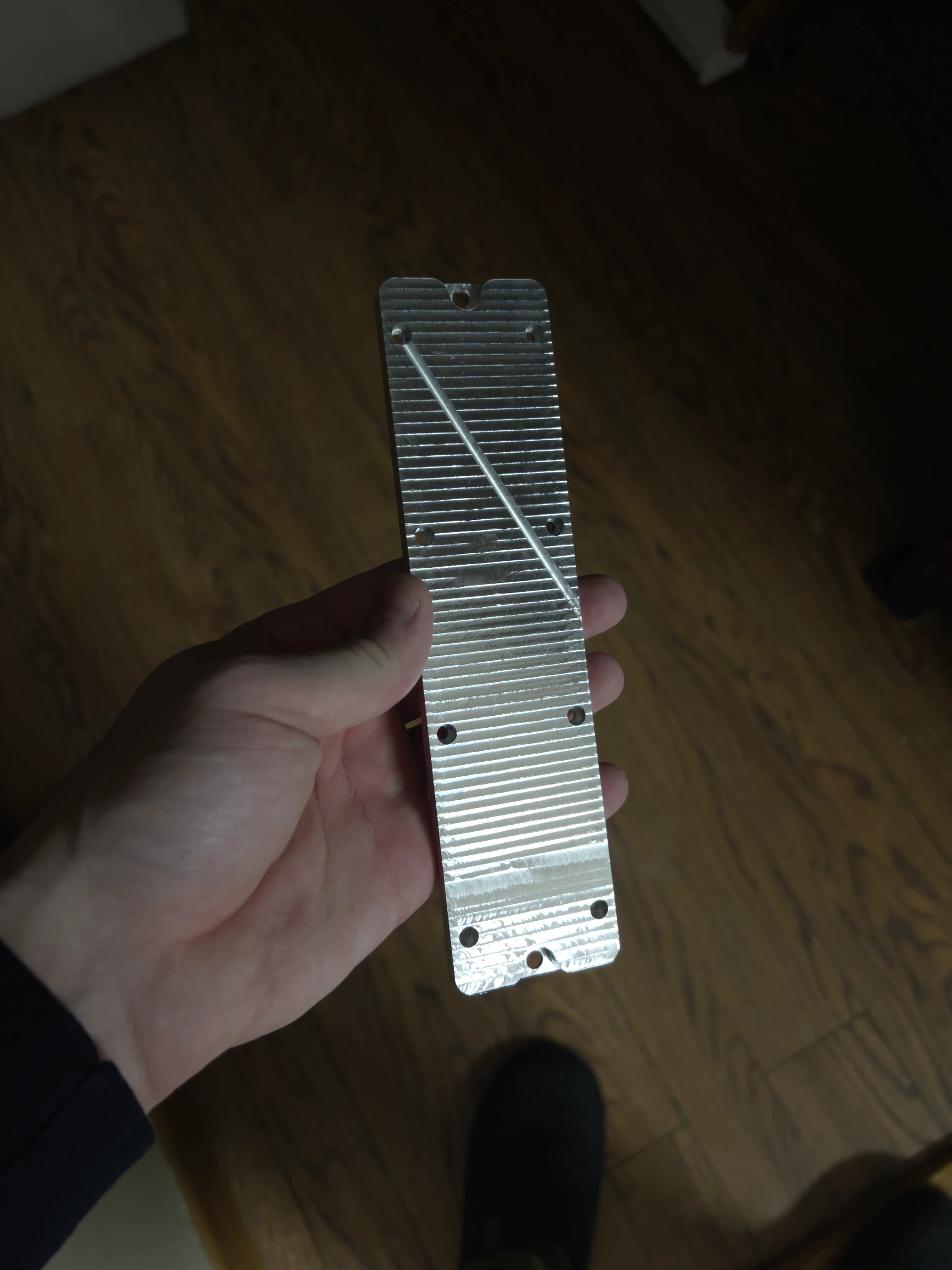
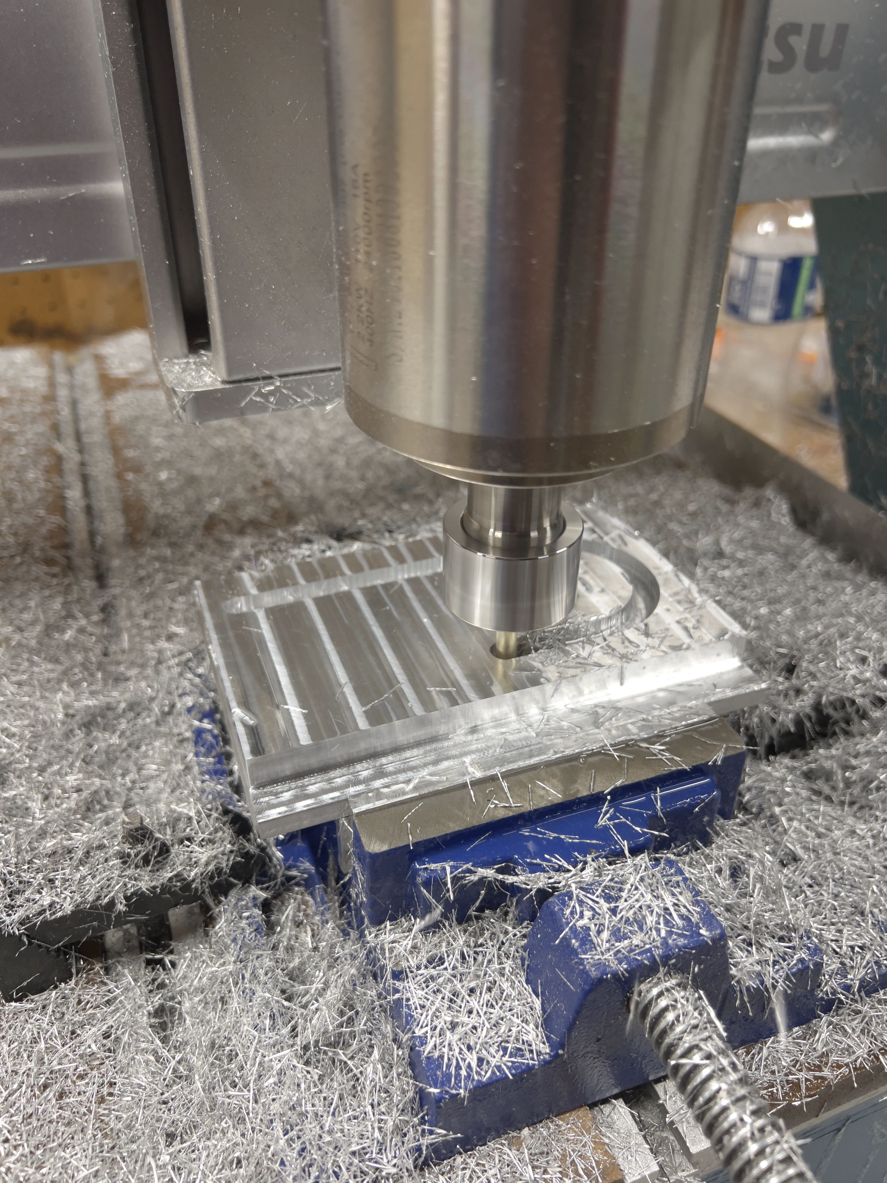
A simple U-shaped coolant path cut with trochoidal milling(dynamic / high-efficiency path for slots). Full slotting loads the tool hard and wants a very rigid setup; a trochoidal path keeps radial engagement low, runs faster, is easier on the machine, and can open a wide slot with a smaller endmill.
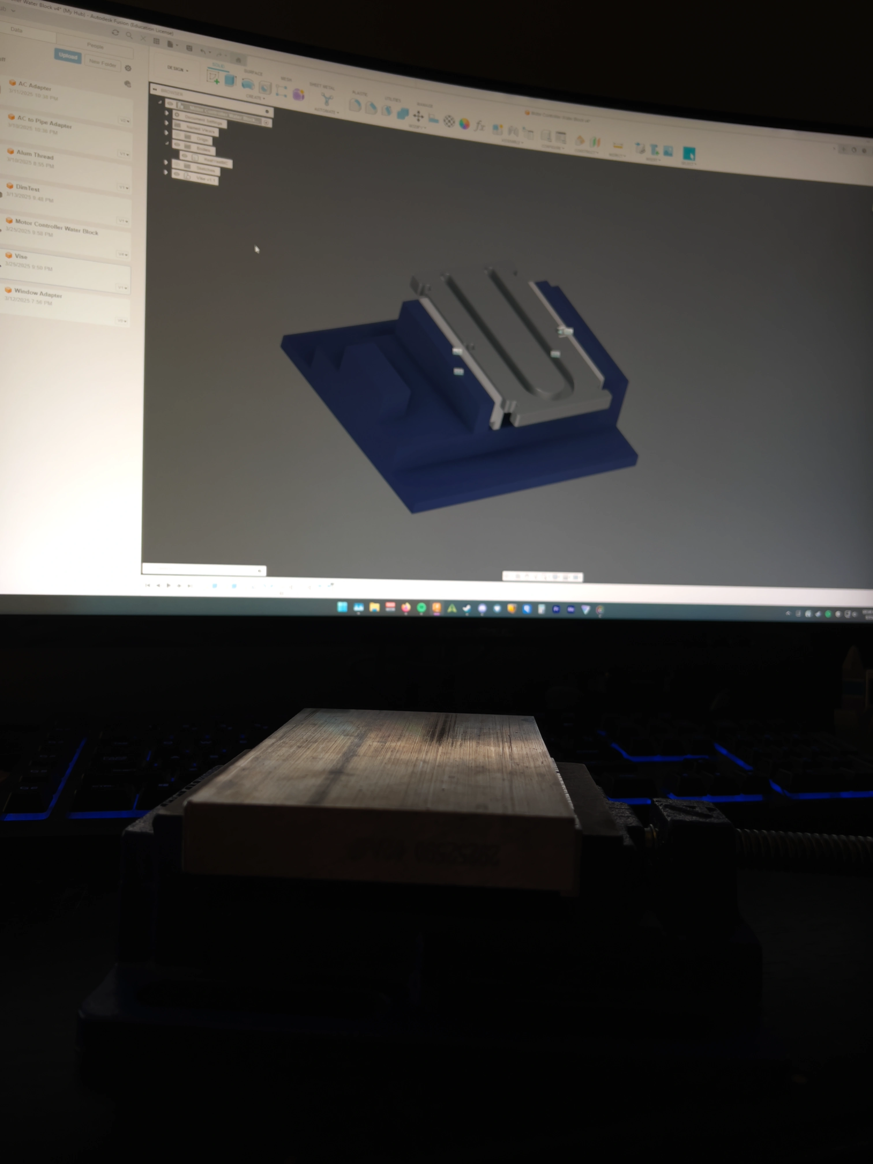
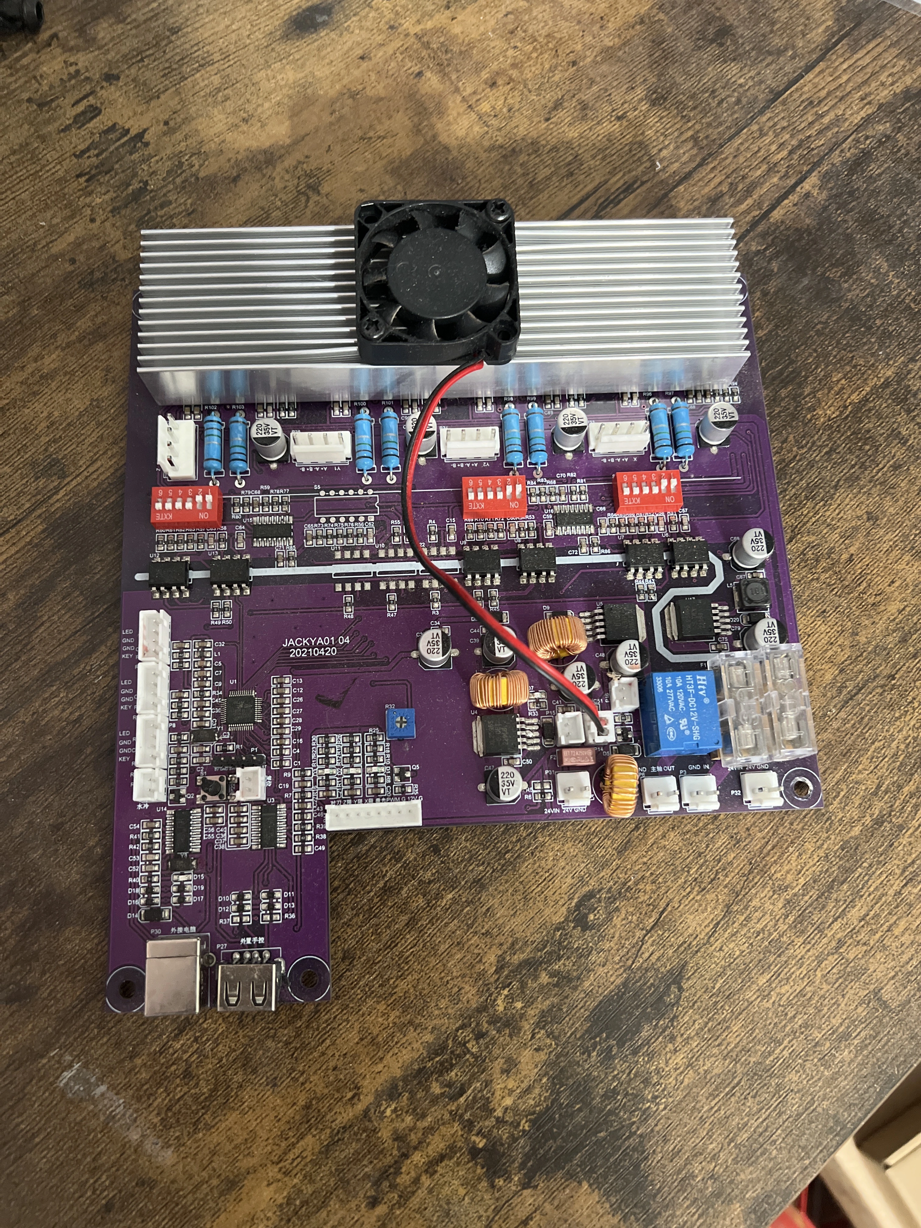
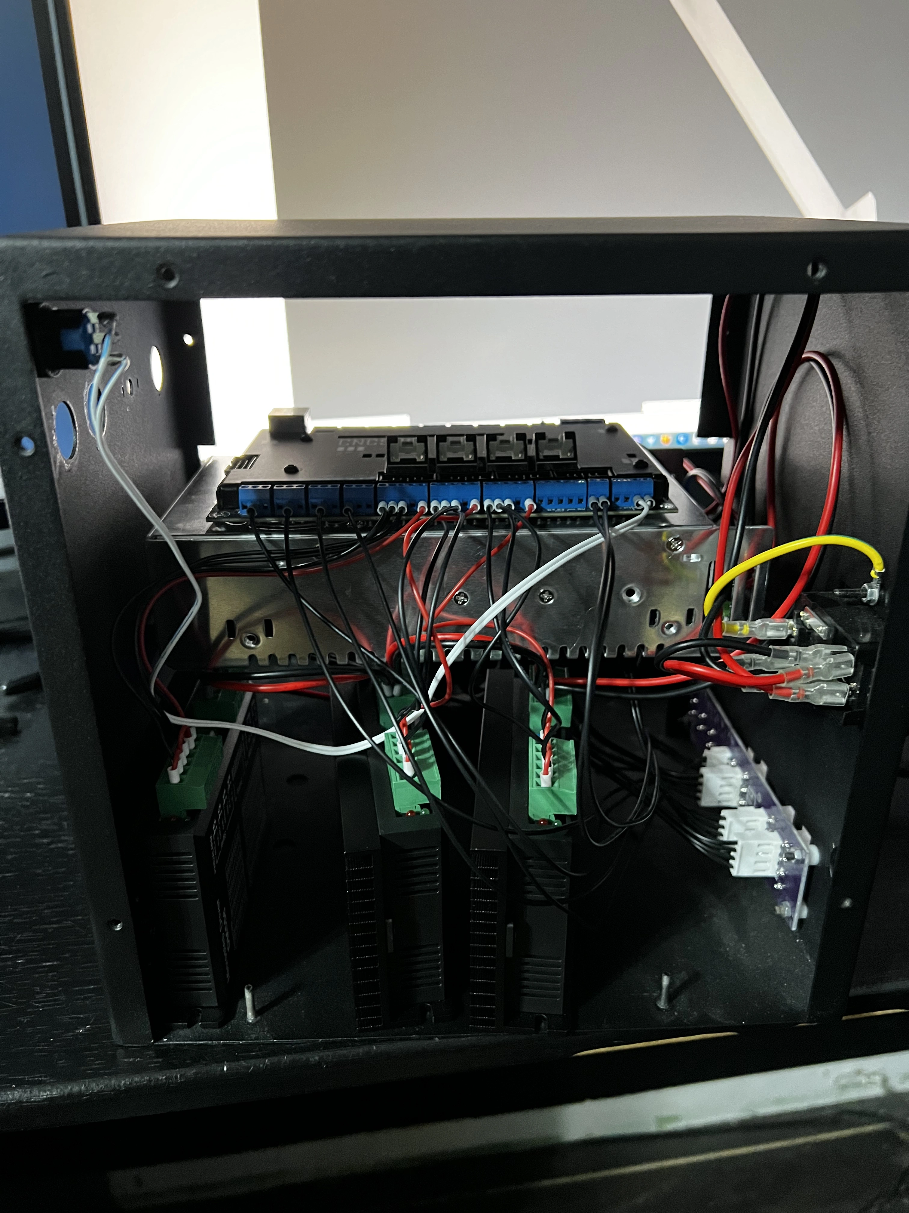
Stock GRBL could not do the subroutines I needed for probing and tool-length offsets, and it was limited as a precision motion brain. I moved to an EdingCNC controller on Ethernet, with separate motor drivers (the old board had drivers built in). More I/O, higher speed headroom, and room for accessories.
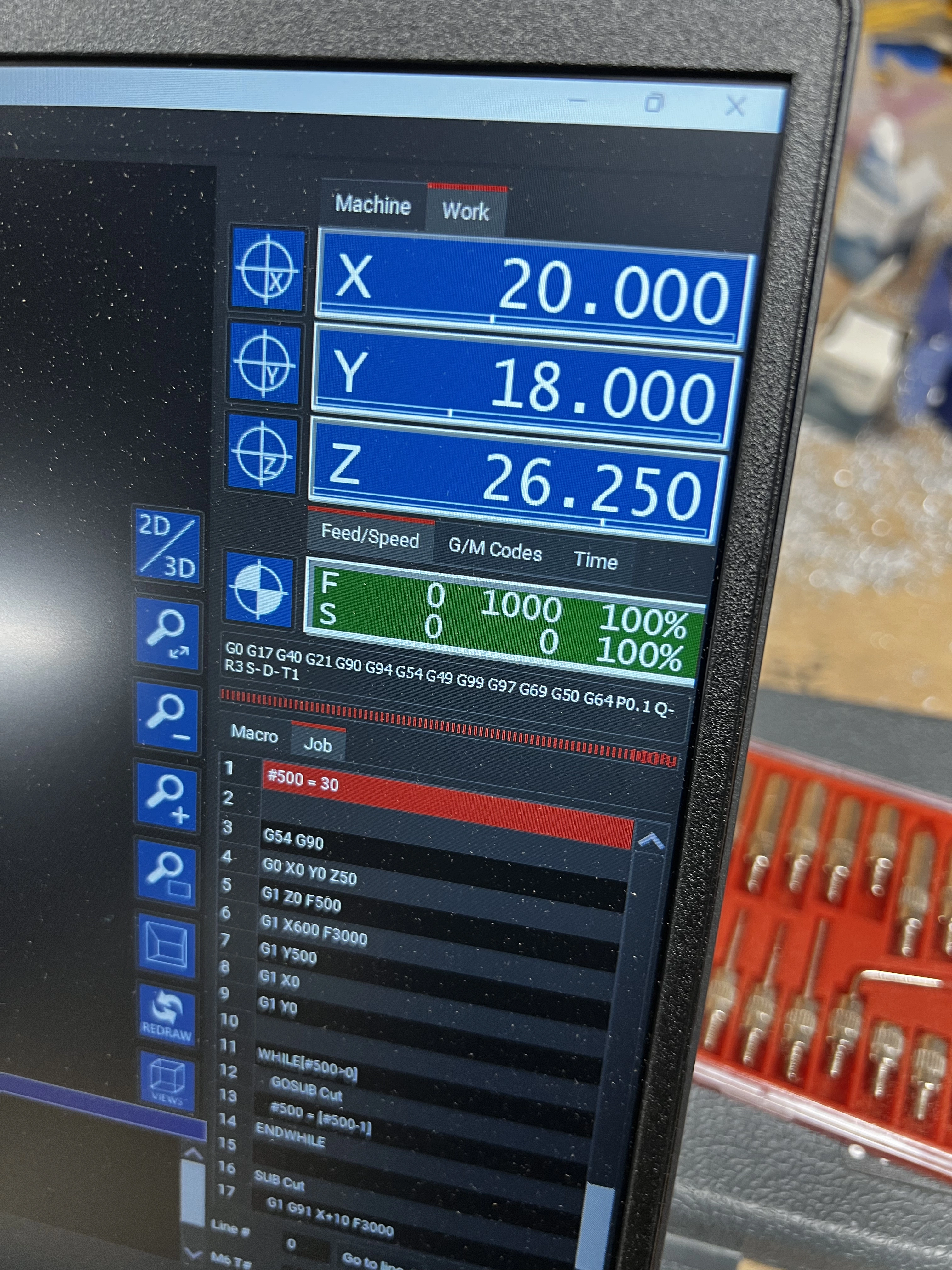
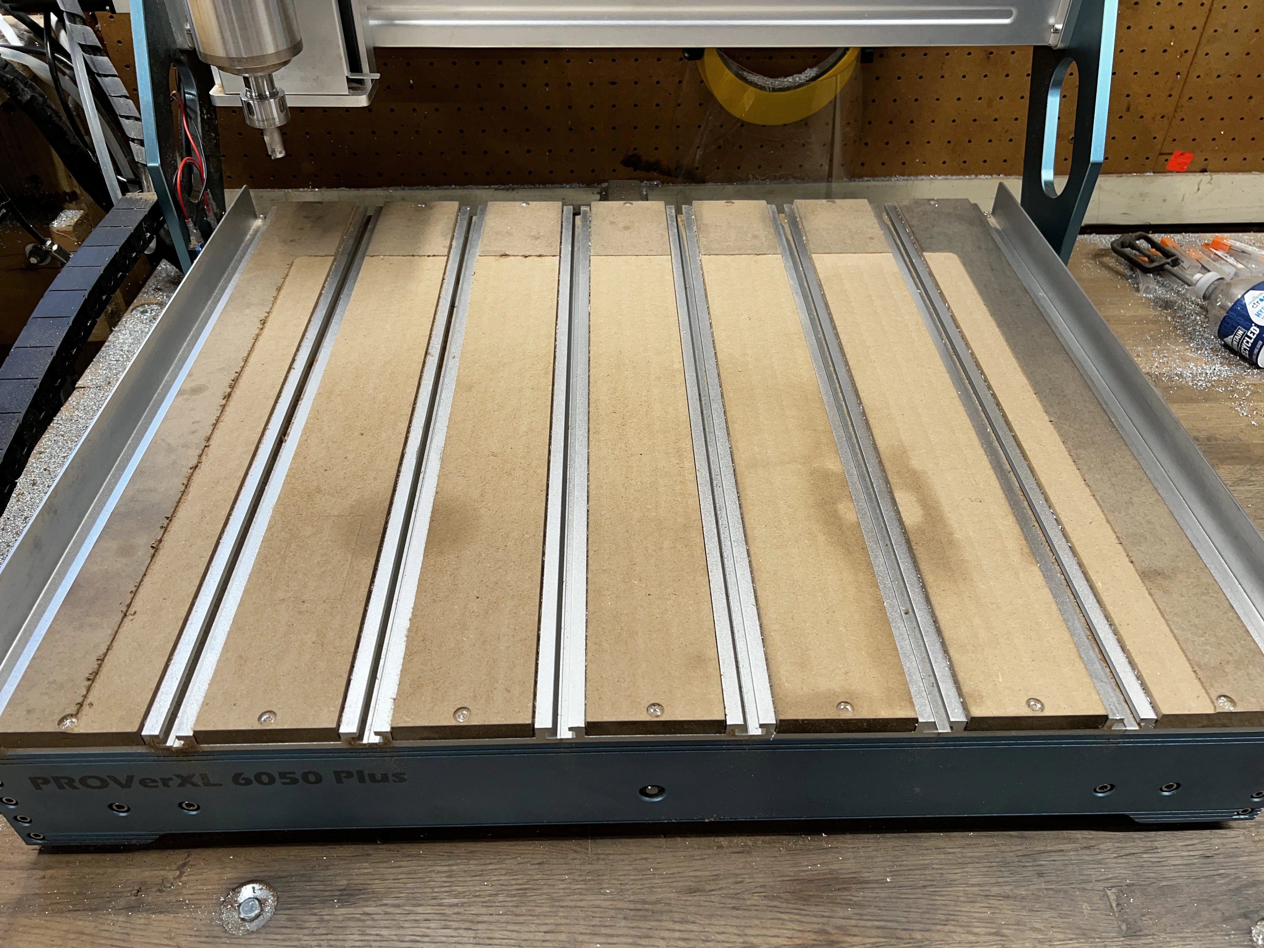
Wrote G-code with subroutines to skim and level the particle-board-style bed so the surface was actually flat before serious work.
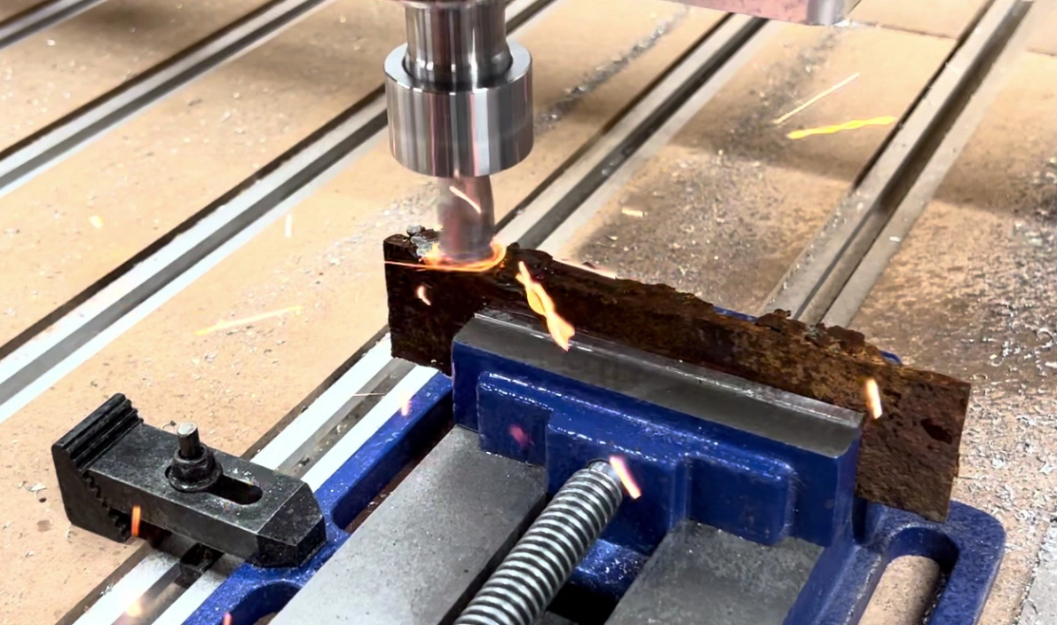
Retested steel with an ~18 mm indexable shoulder mill and more aggressive engagement. Mystery steel cut at a respectable rate. Sparks are normal; my “coolant” at the time was alcohol (fine for aluminum). On ferrous cuts it ignited. Lesson: non-flammable mist or flood for steel; alcohol only where fire risk is managed, mainly aluminum.
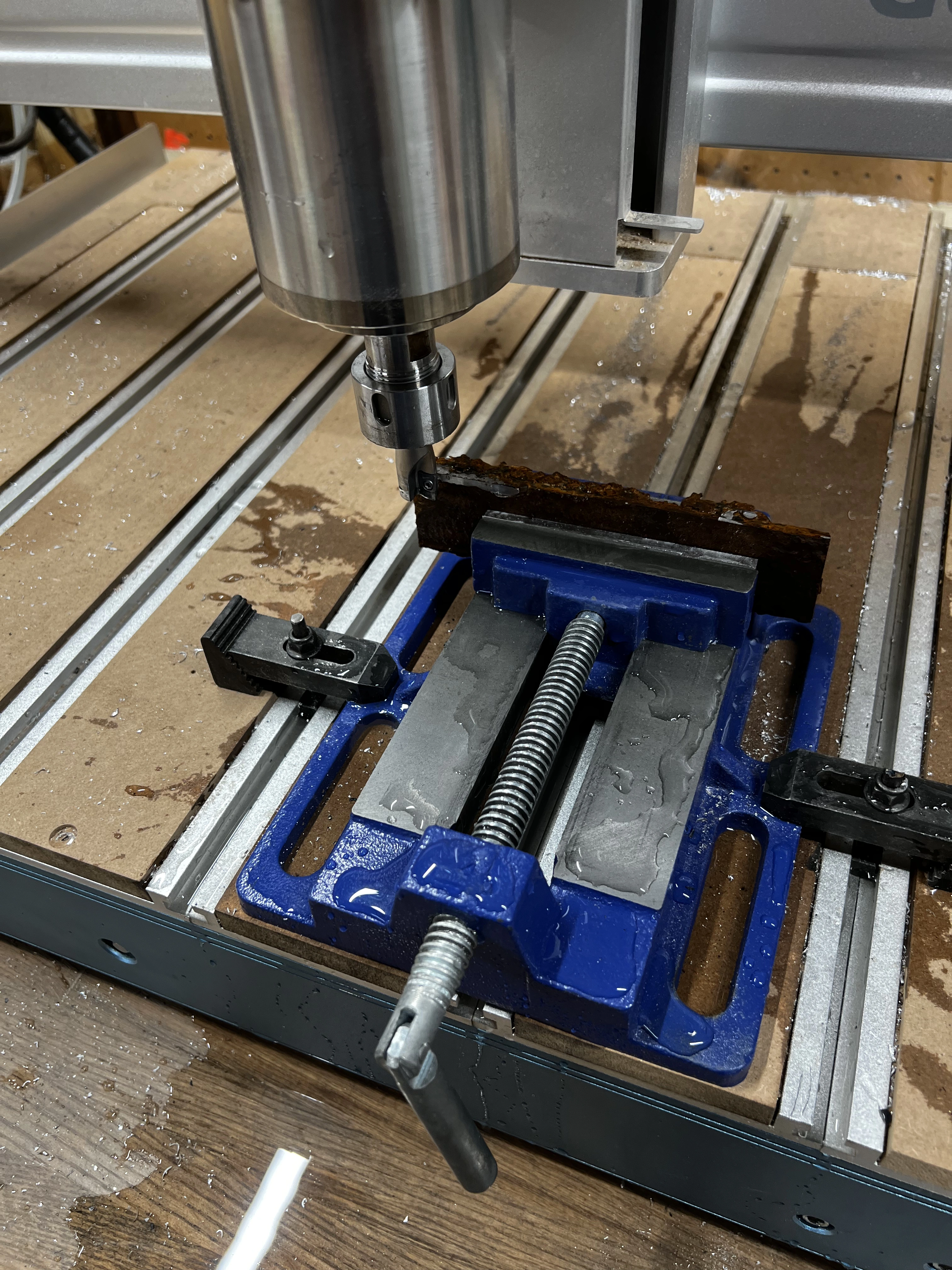
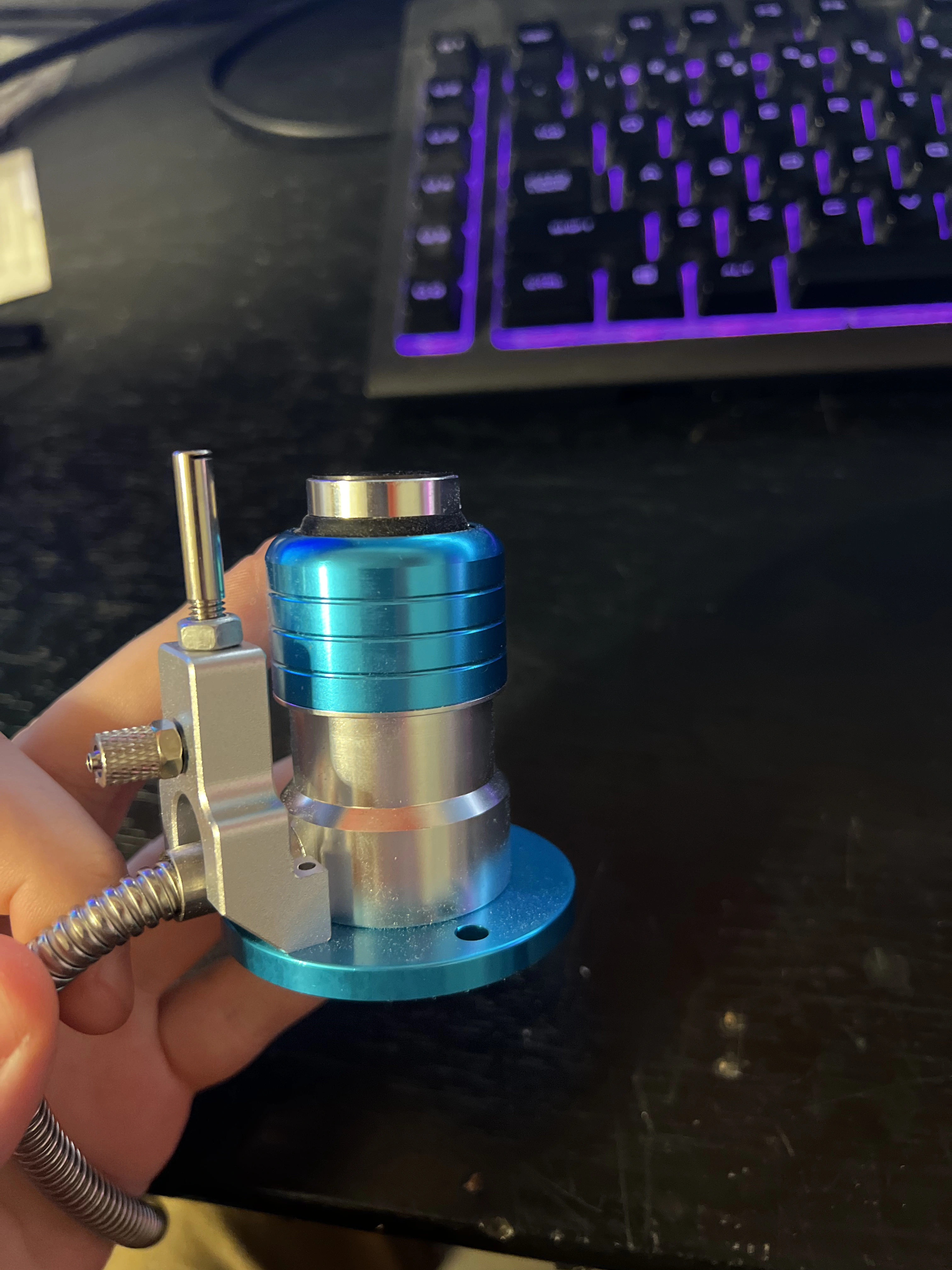
Amazon mist unit + air compressor + a 3D-printed adapter. Flood cooling can wait until the machine is more sealed; mist is enough for now.
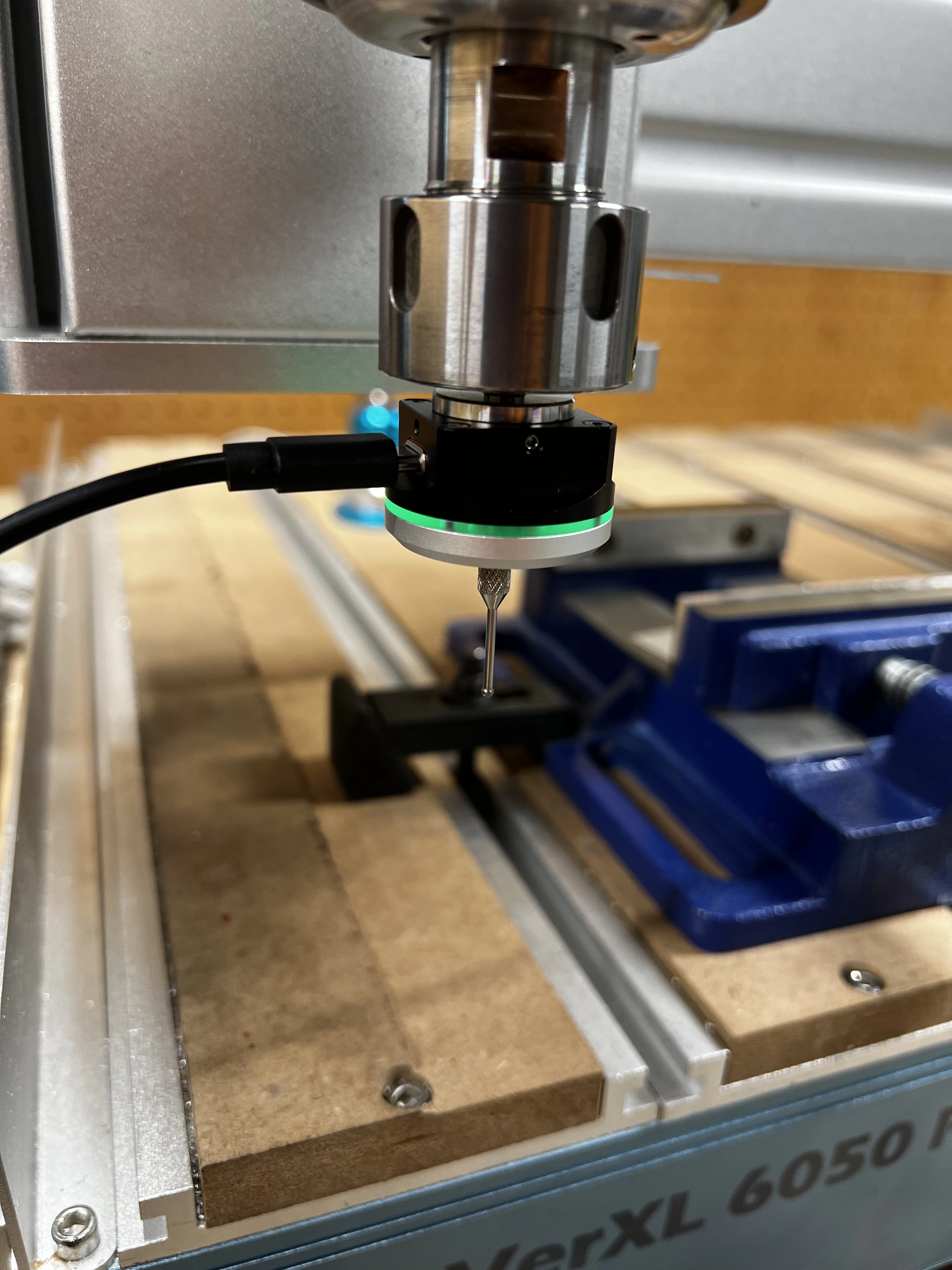
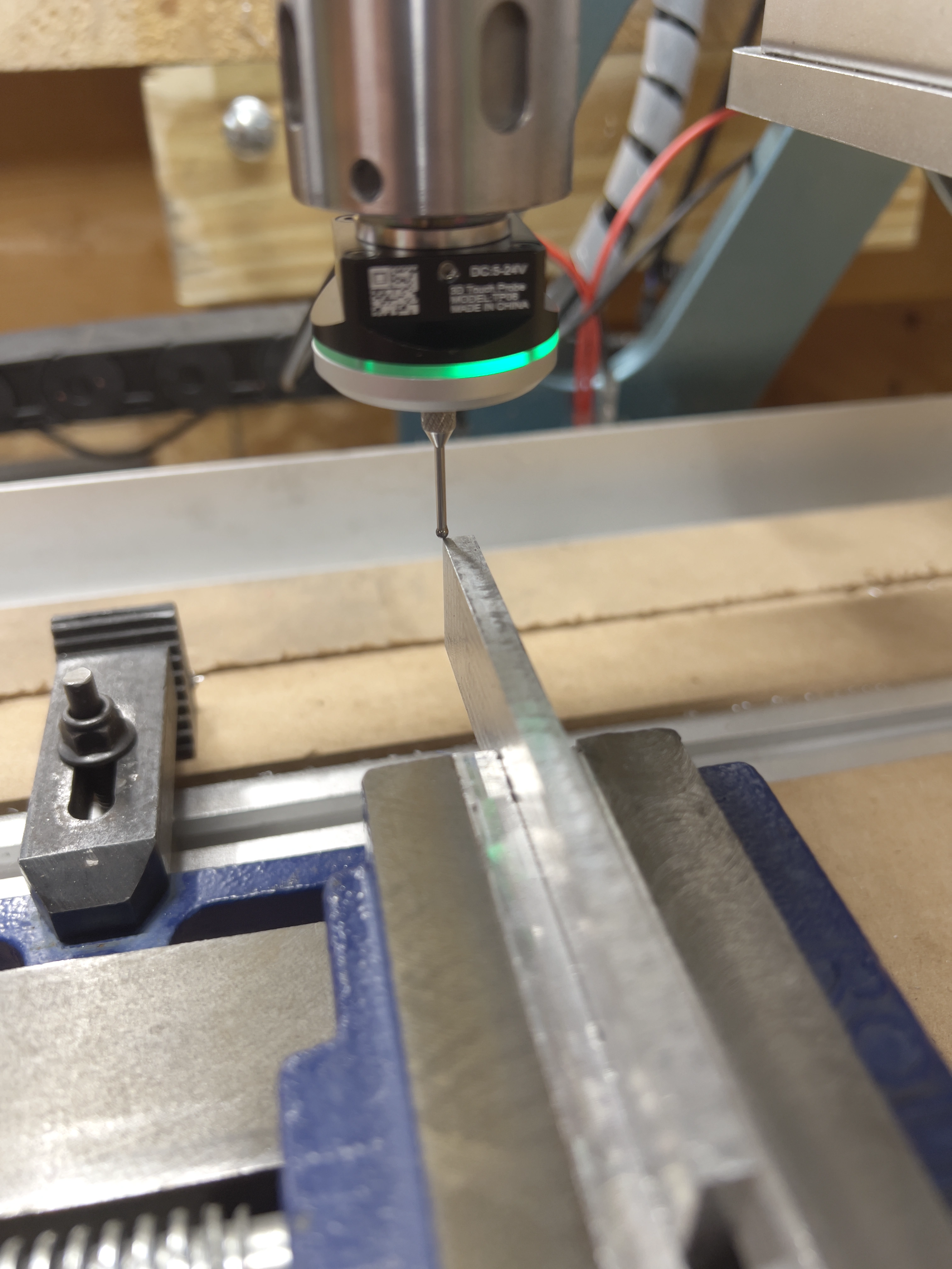
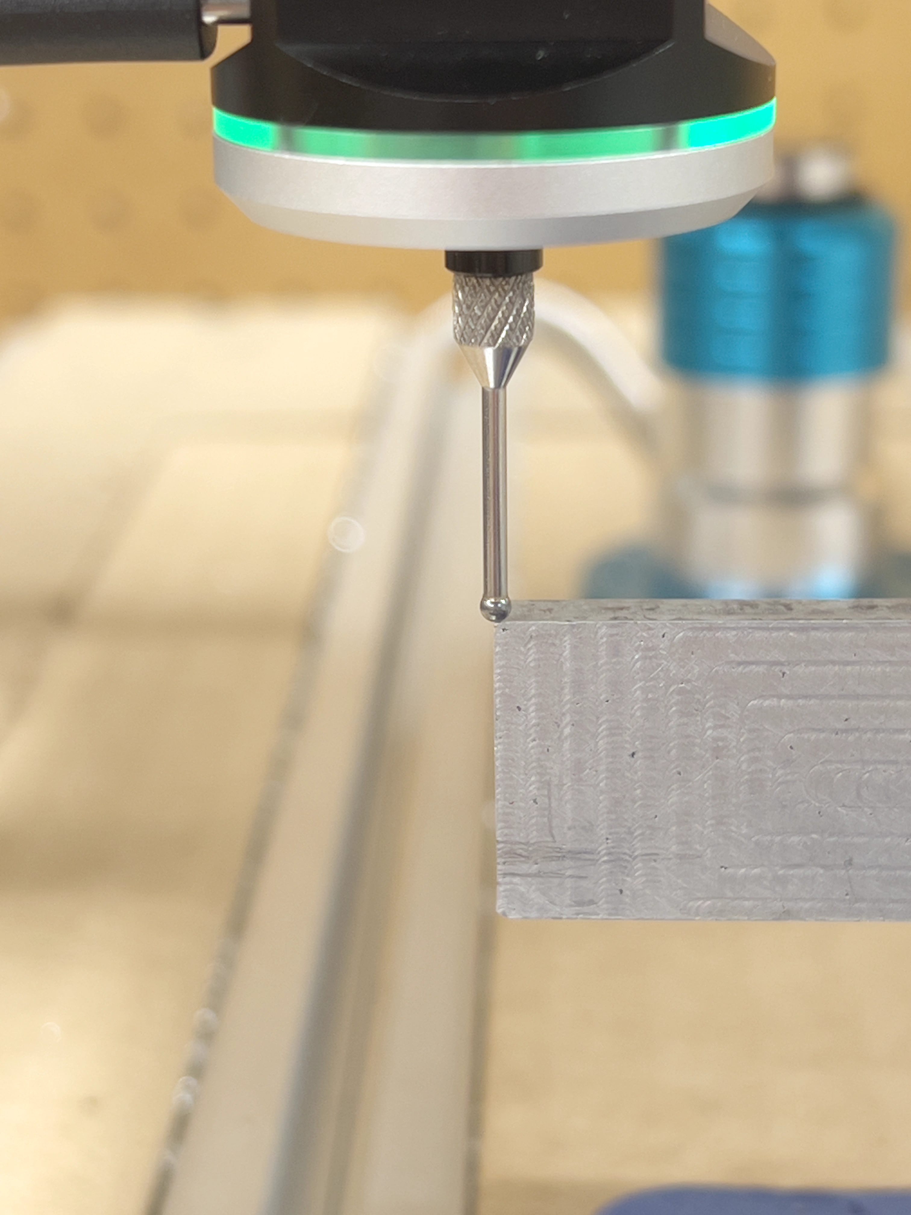
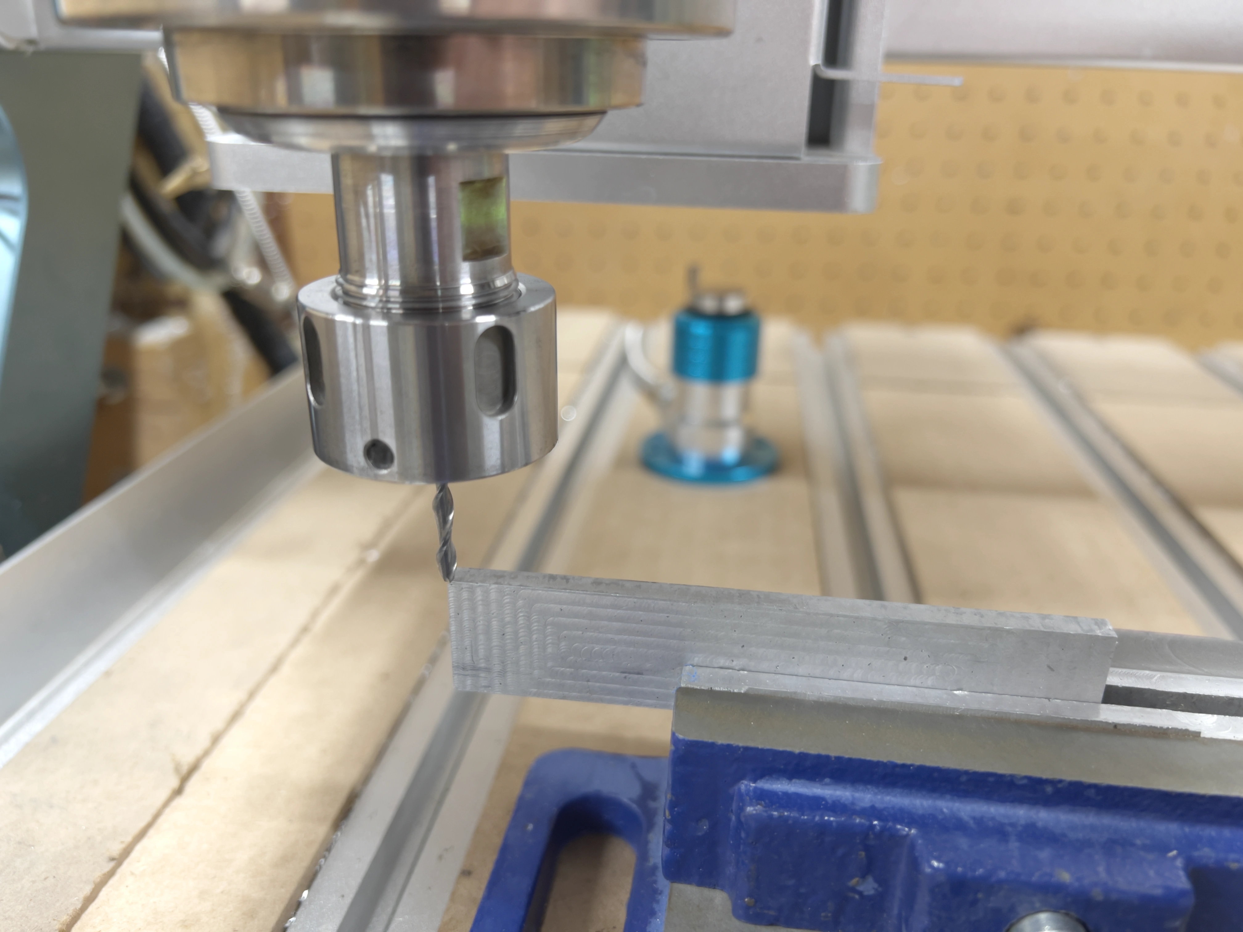
With EdingCNC in place I added a tool setter (tool-length probe) and a 3D touch probe, then spent a few evenings on subroutines: move to the setter, measure length, apply offset, change tools, measure again. Probe repeatability is about0.01–0.02 mm. That fixed a lot of the Z inconsistency from manual touch-offs.
The aluminum jaw clamp eventually fatigued. The replacement was too tight, the jaw would not move cleanly, and the vise failed. Same model again, lighter screw torque, then an evening of planing / tramming / squaring so it sat true.
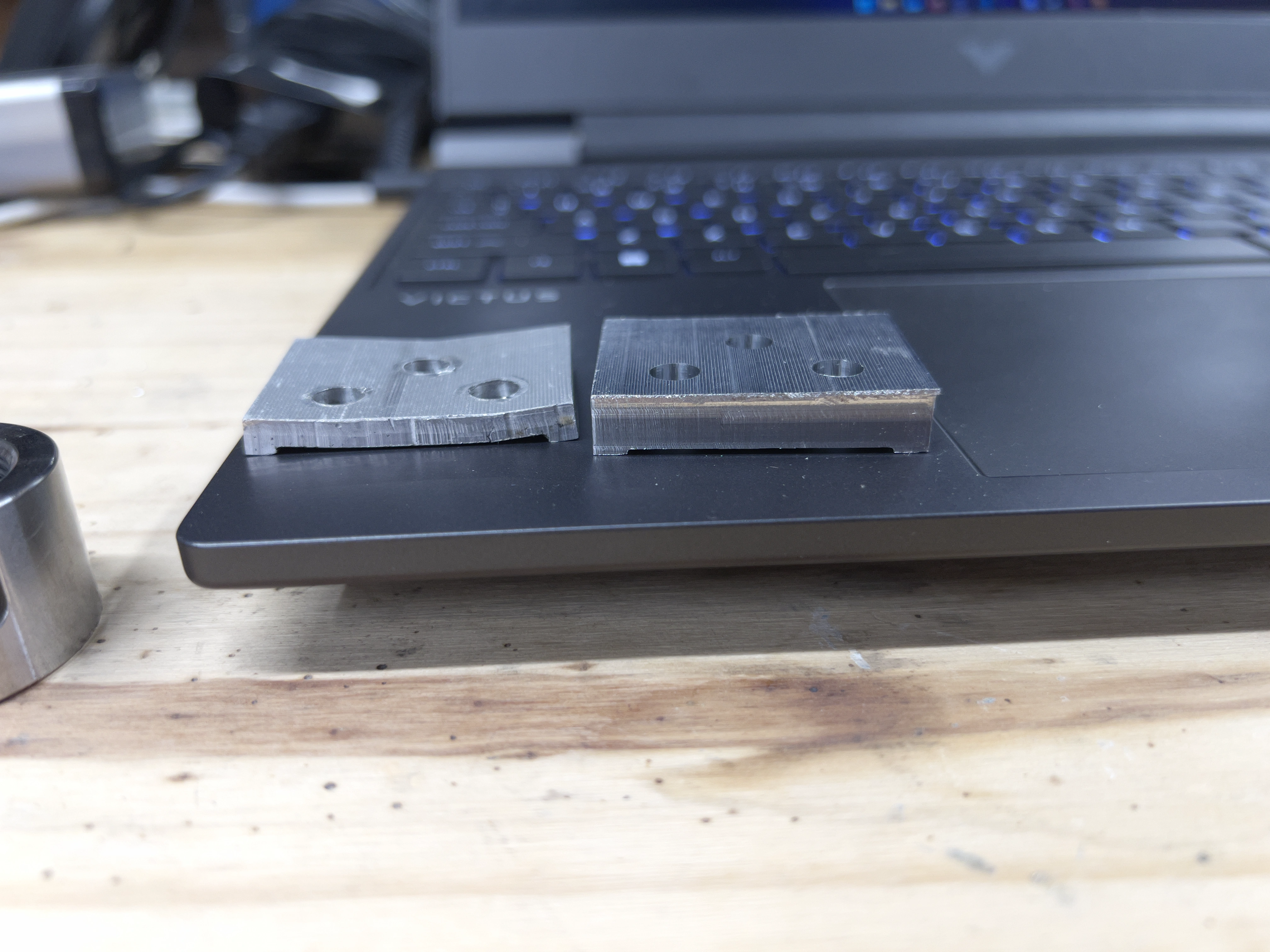
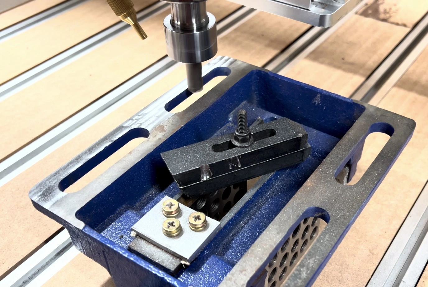
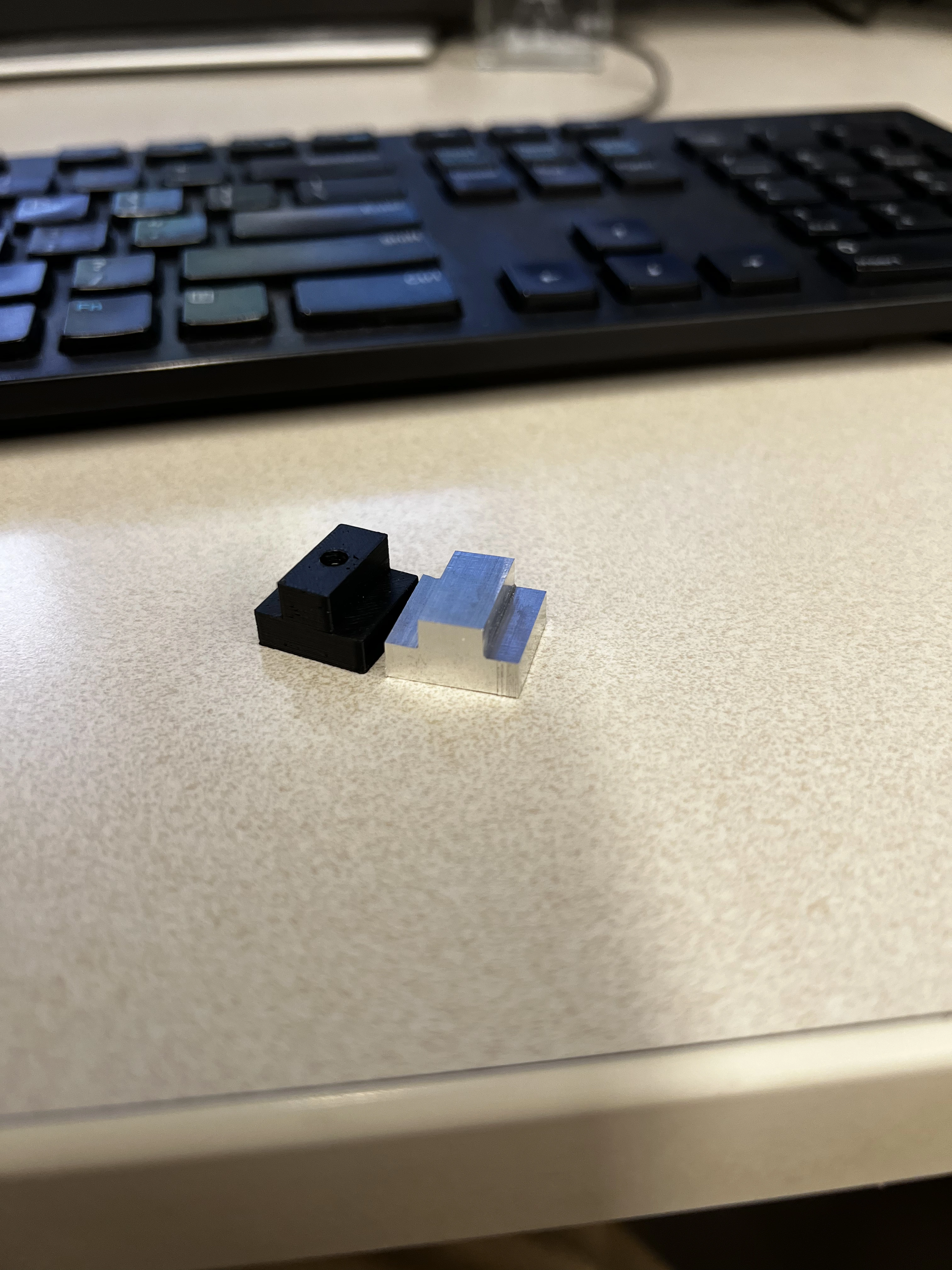
Running out of T-nuts for the bed slots, I printed a test, then CAMed the real ones in Fusion 360. Results were nearly perfect: under 0.01 mm on X/Y and under 0.02 mm on Z (~0.0004 in and ~0.0008 in). One blank shifted in the vise and went slightly off, but the machine itself had clearly gotten more consistent with backlash awareness, probing, and better process.
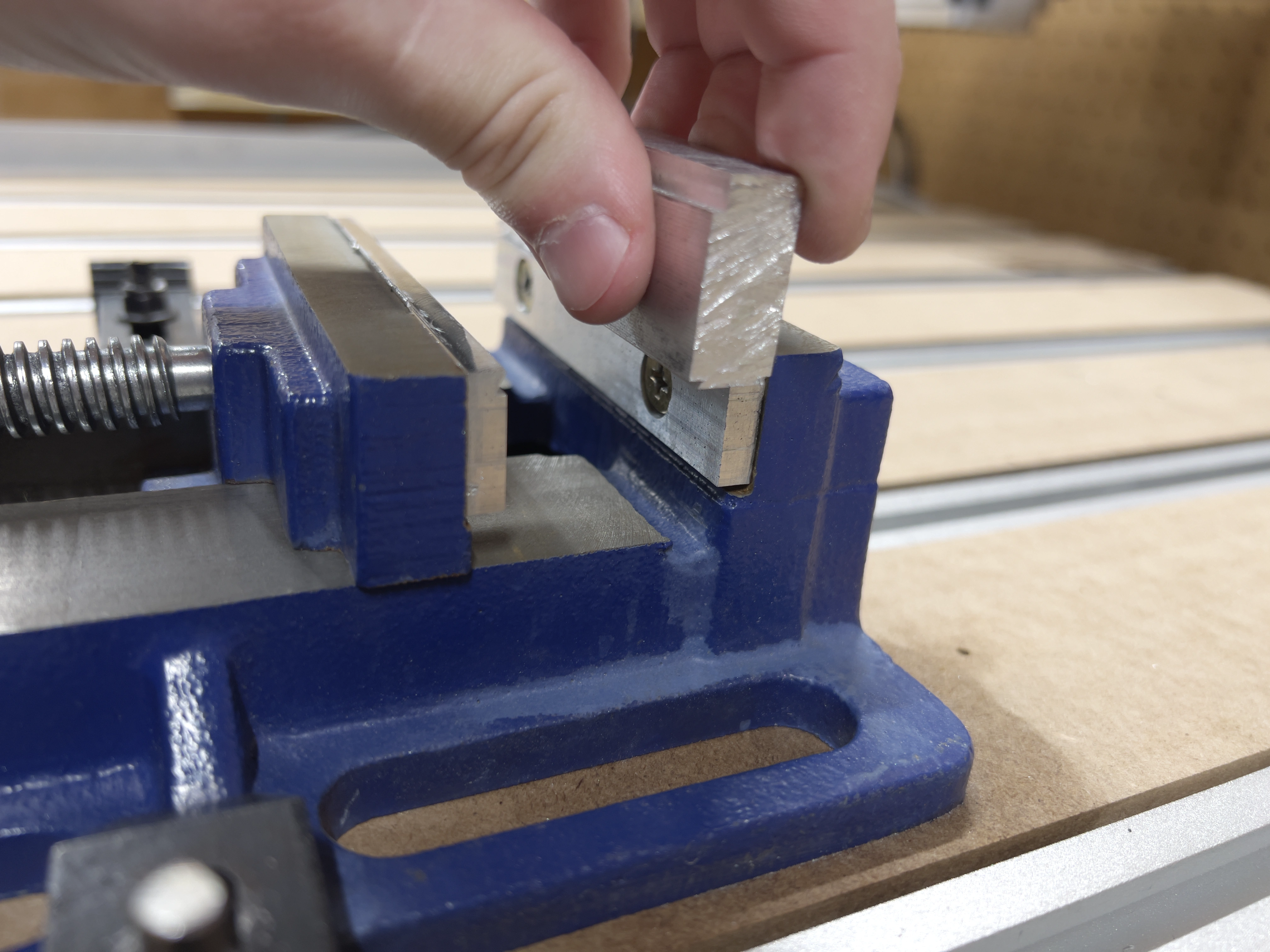
Latest workholding step: a dovetail cutter and matching angles in the vise jaws. Cut a dovetail into the stock, drop it into dovetail jaws, and the part is mechanically locked — much stronger grip than friction alone. That high clamp load at the top of the jaws is also what helped kill the first jaw clamp before I understood the failure mode.
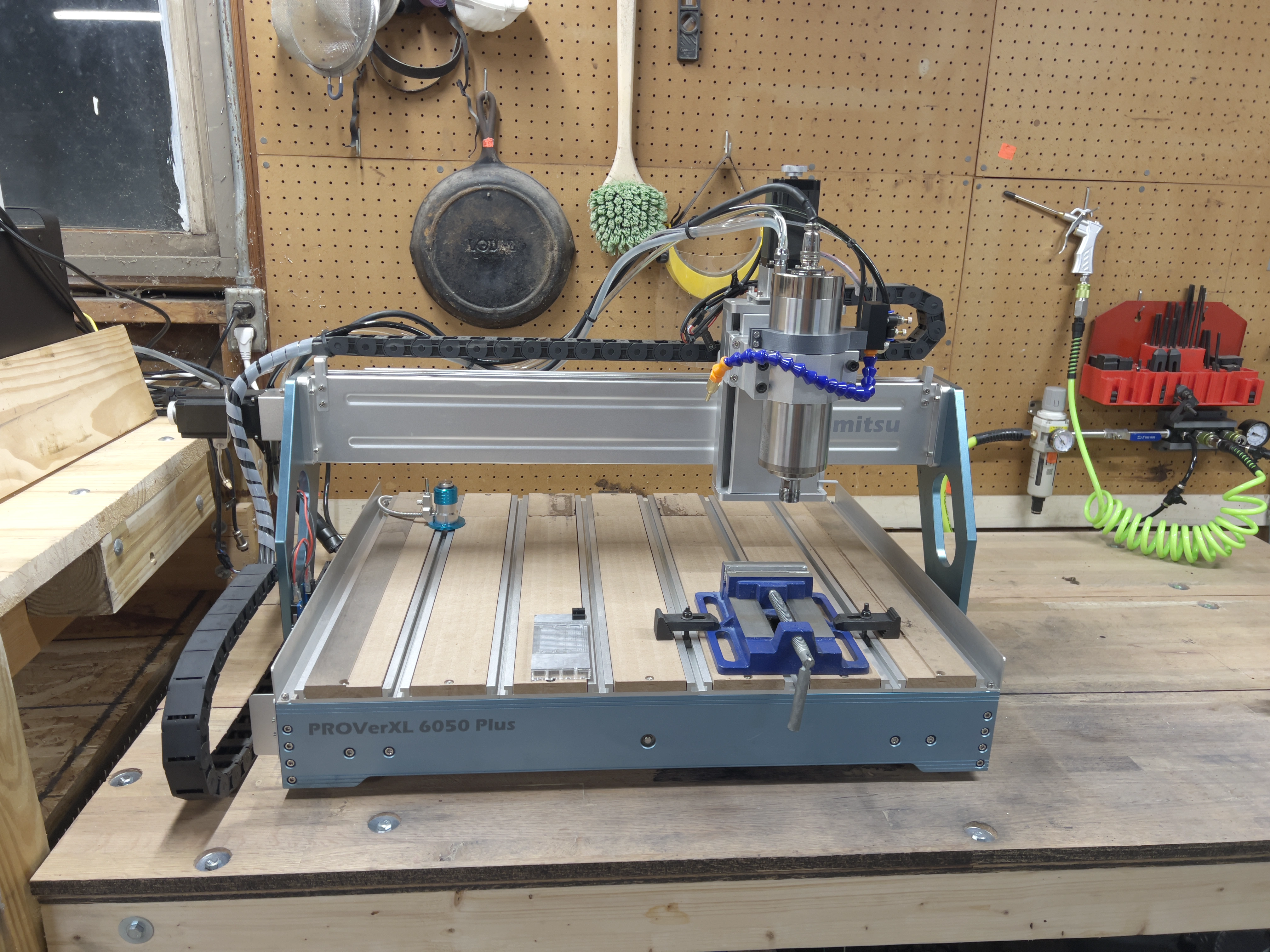
The router cuts aluminum in ways the stock machine could not. Spindle, gantry brace, rigid spindle mount, EdingCNC, probe, tool setter, mist, and better workholding are in place. Remaining limits are mostly the motion system — especially Z — and how far I push ferrous cuts without a proper coolant setup.
Typical feeds are 2000–3000 mm/min with rapids at 3000 mm/min; open-loop steppers lose steps if pushed harder. Finish passes drop to 500–1000 mm/min when the surface matters.