I need more torque and most motors for sale cost more than I'd like to pay so I decided to make my own. Besides, motors are one of the simplest machines... right?
In this project I focus on solving a problem presented in my first ever project, the E-Bike. In that project my motor was unable to provide adequate torque at low speeds to get the bike moving from a standstill, but was otherwise able to accelerate the bike up to 30+ mph on flat ground.
My initial searches of how a motor works and how to design one resulted in pretty straightforward geometry that looked simple enough to 3D print. Since I had used my printer to great success elsewhere on the E-Bike project, I figured I'd try to 3D print a motor. Besides, the only tool I had to make precision prototypes was the printer, so it would have to do.
After finding out that the motor I bought for the E-Bike wouldn't work without using an extreme gear ratio (due to the low torque and thus high speed needed to get useful power from it), I figured this motor should be optimized for torque at a low RPM.
Axial-Flux motors excel in this area, and at the time I knew of another company making these motors. Quite frankly, the designs seemed simpler to produce than a typical radial flux motor. The additional benefit of the Axial-Flux motor is that it also has more torque given the same diameter as a Radial-Flux machine, due to physics alone — the coils and magnets are placed further away from the axis of rotation.
Capabilities and Criteria:
Initially I planned to manufacture this motor using additive manufacturing, as this is what I had access to. Eventually, when the design evolves enough and is constrained by material selection, I intend to move to casting or machining so I can utilize metals.
Why does the manufacturing process matter when it comes to the design of the part(s)? Well, it turns out that some geometry is impossible (or extremely difficult) to create using certain manufacturing processes.
In additive manufacturing (3D printing, and even welding), material is added until the part comes into existence from nothing. In subtractive manufacturing — milling, routing, laser/water cutting, turning — you start with more material and remove it until you're left with the final geometry. This is analogous to starting with a large marble block and slowly chipping it away until the statue that was hiding inside is revealed. Additive manufacturing is more like taking a hot-glue gun and slowly stacking beads of glue until you can finally hold the thing you made.
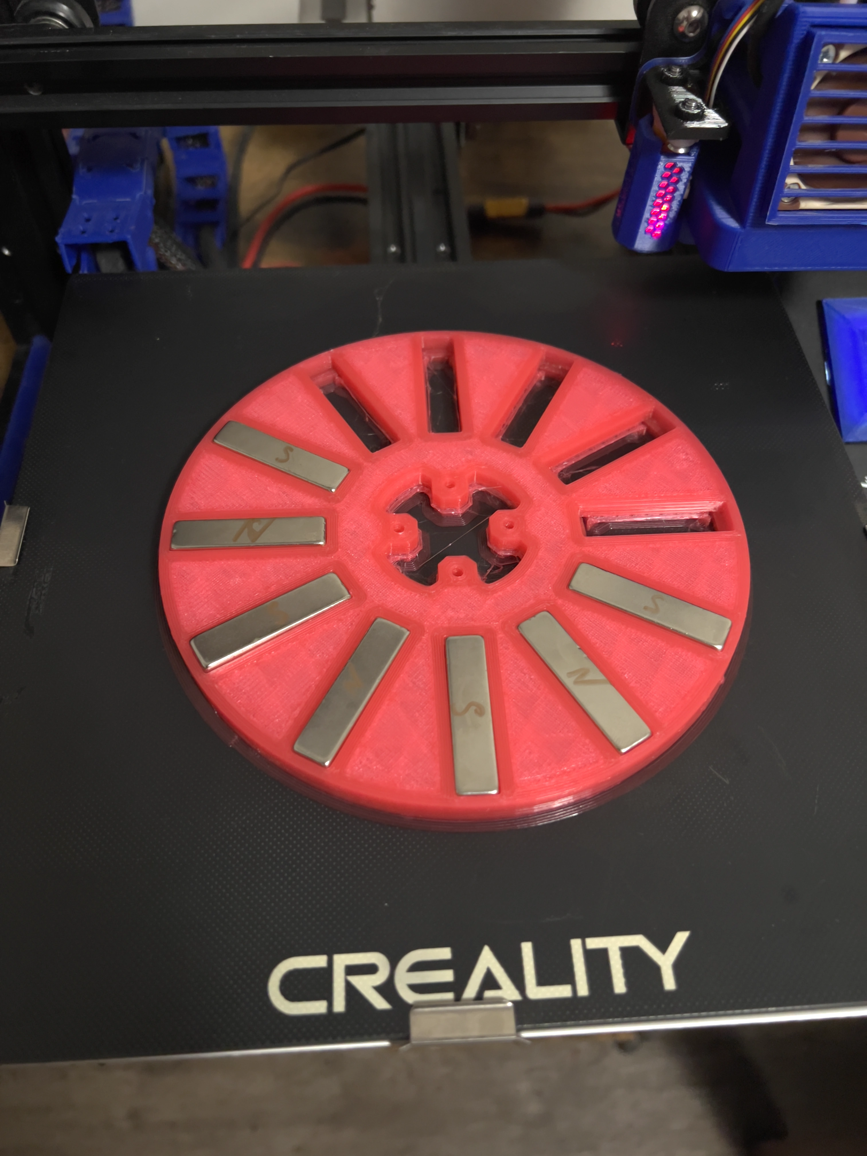
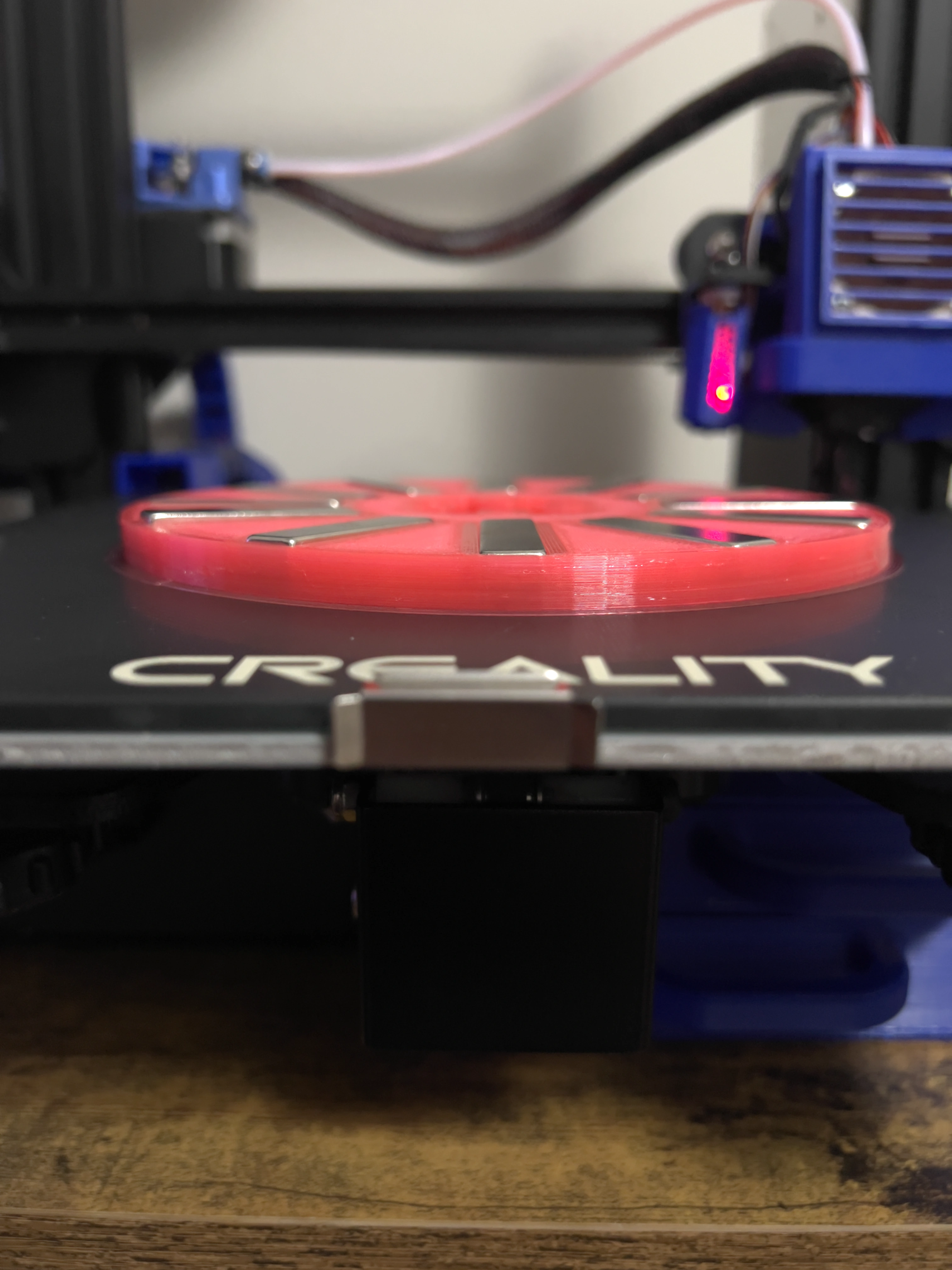
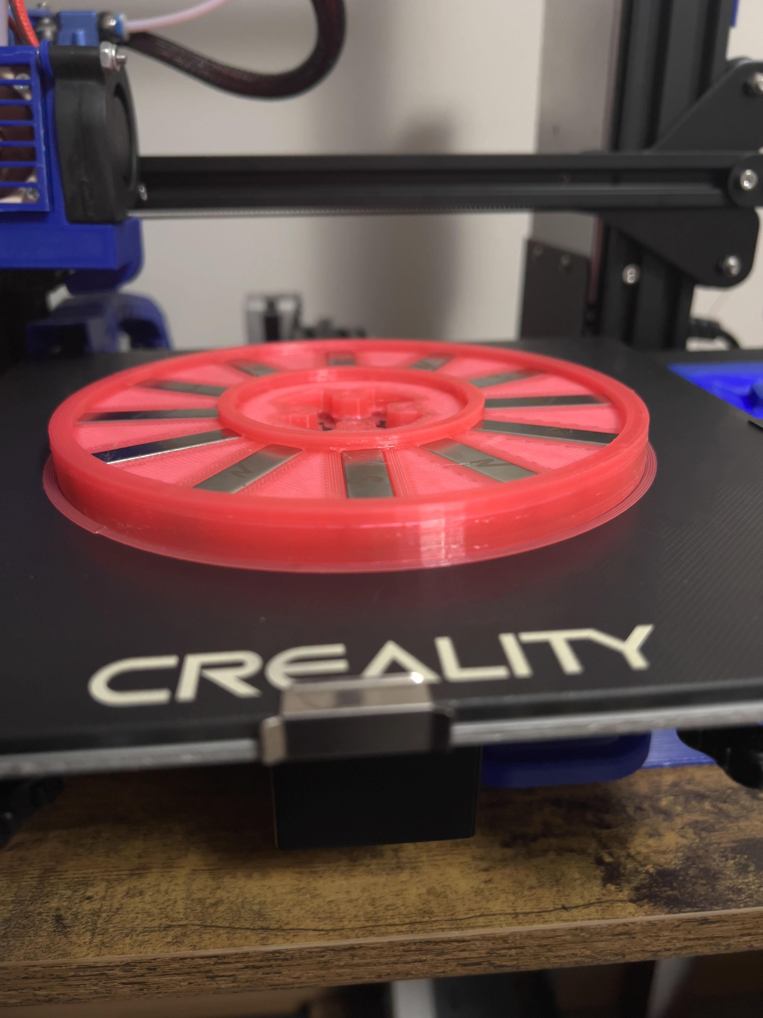
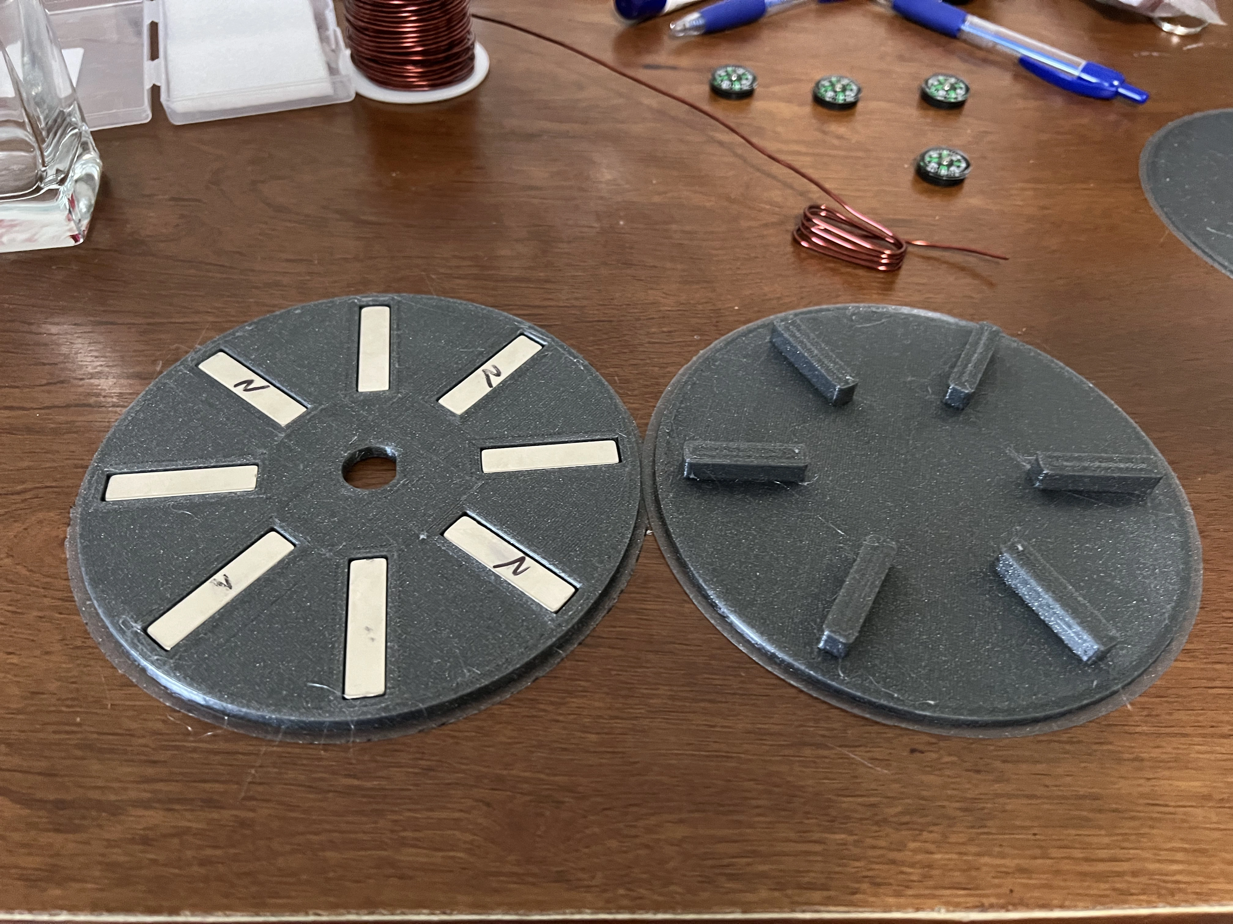
Early rotors used this pause-and-embed method: stop the print, drop magnets in, resume so the plastic locks them in. It works for printing, but it’s almost impossible to machine later — which is why the design eventually moved to open slots with covers.
The core challenge here was that I didn't fully understand how motors work. Even though they are relatively simple machines, all the pictures of radial flux motors being produced made them seem complex and difficult to manufacture. Ironically, radial machines were mass-produced specifically because of their ease of manufacturing.
This meant I had to spend more time looking at a wide range of examples. I also knew my initial prototype needed to stay technically simple so I could test whether motors were actually simple in reality, or if the diagrams I was studying were oversimplified.
Using a 3D printer meant I was limited to plastic filaments, and these materials are not the most robust for motor components. The rotor could spin at high speeds, and I wasn't sure whether the plastic would hold up or fail violently. The magnets added significant rotational mass, increasing the risk of failure if spun too quickly.
The coils were copper, but the coil holders were PLA. PLA begins to soften (glassify) around 40–60 °C, which caused the coils to lose their shape under load. The stator was also PLA. Under the strong attraction between the coils and magnets, the PLA would bend, making the air gap uncertain. In one test the stator and rotor actually contacted each other, created friction heat, and welded themselves together.
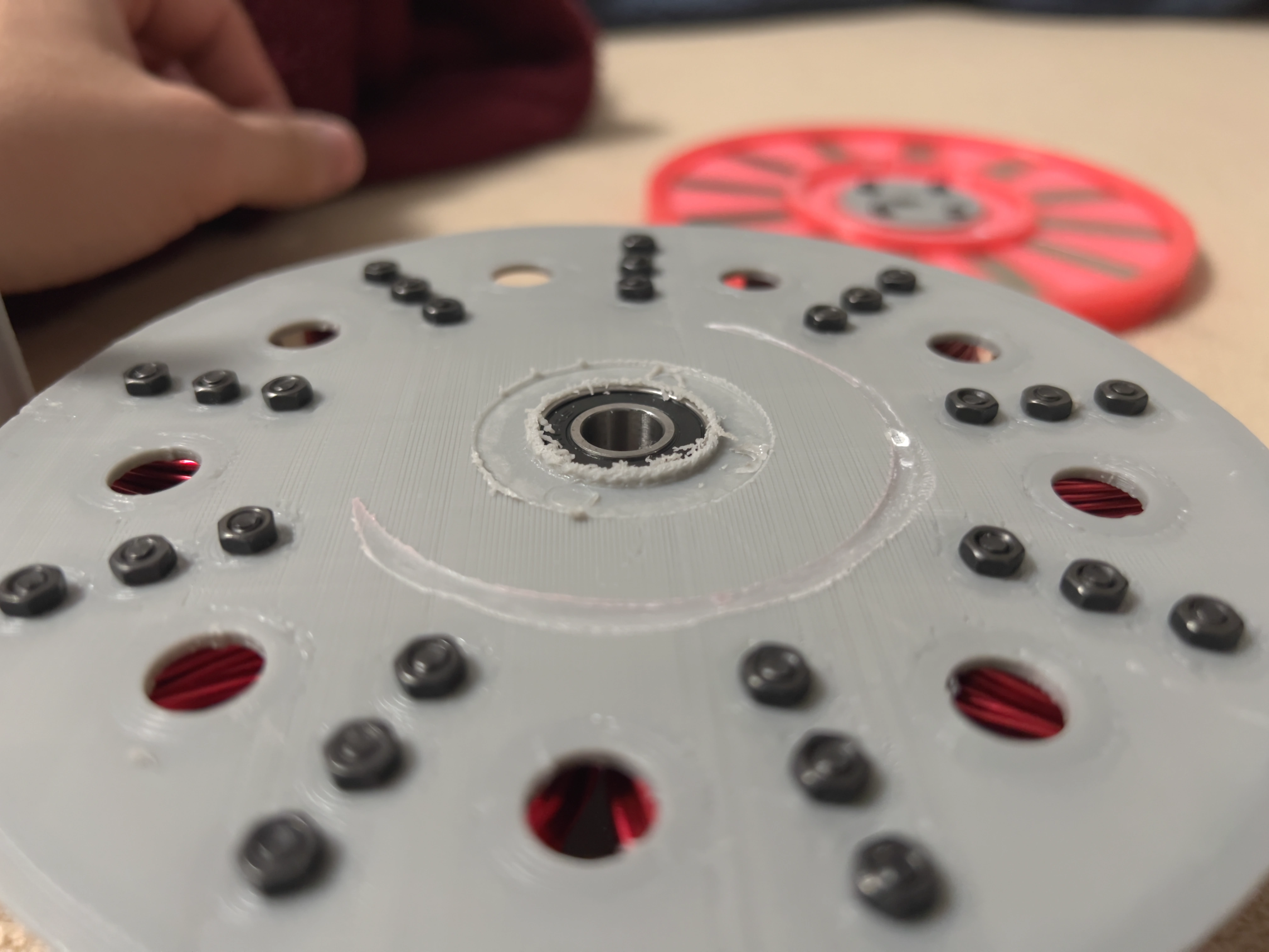
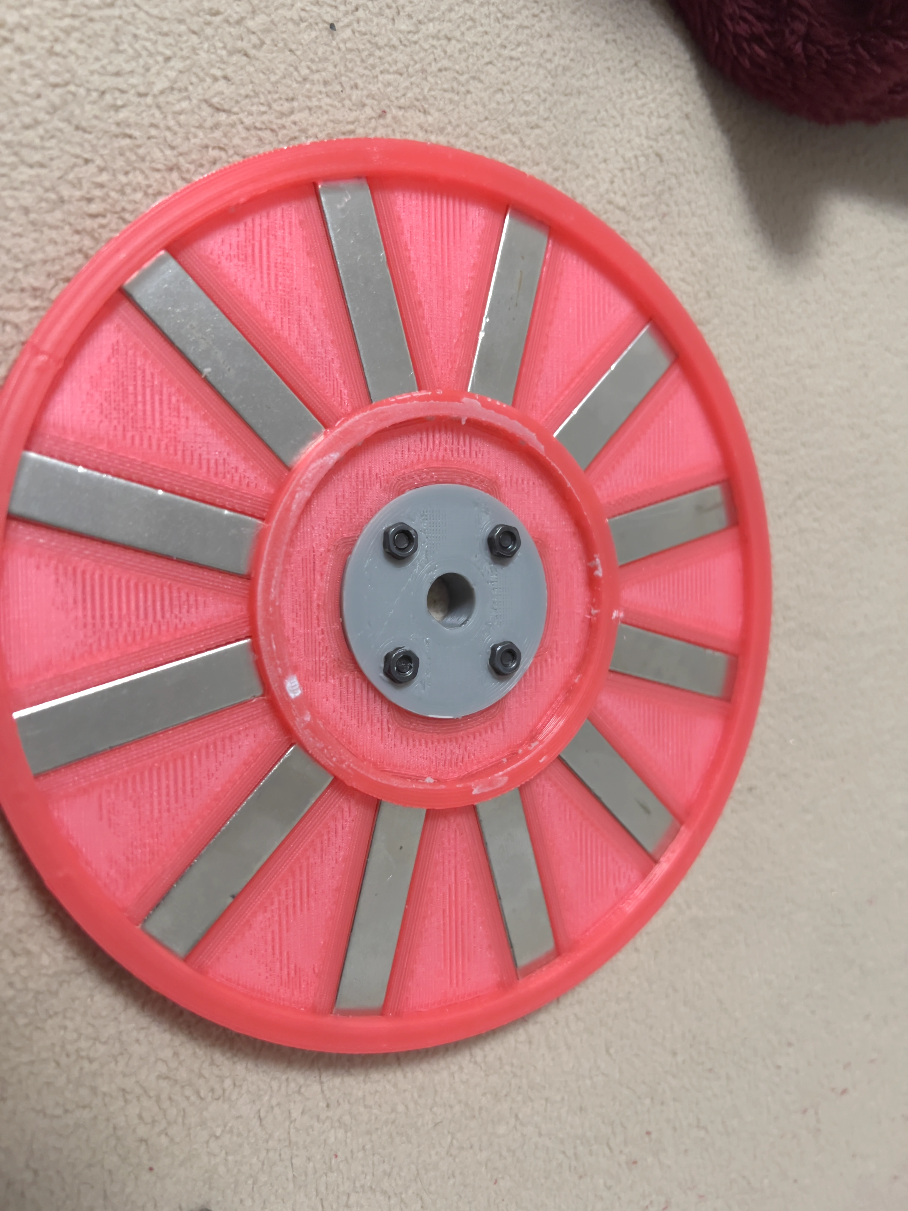
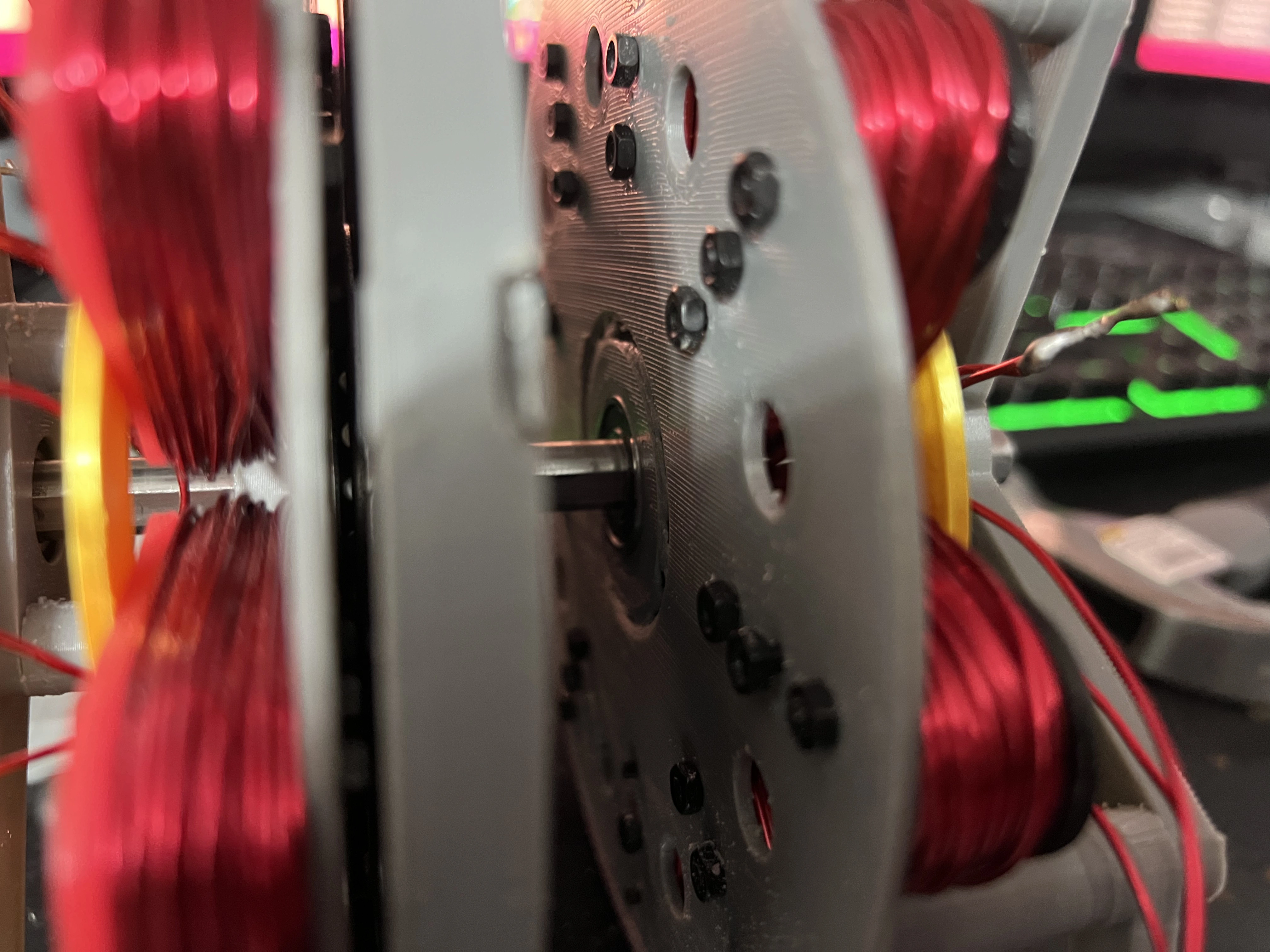
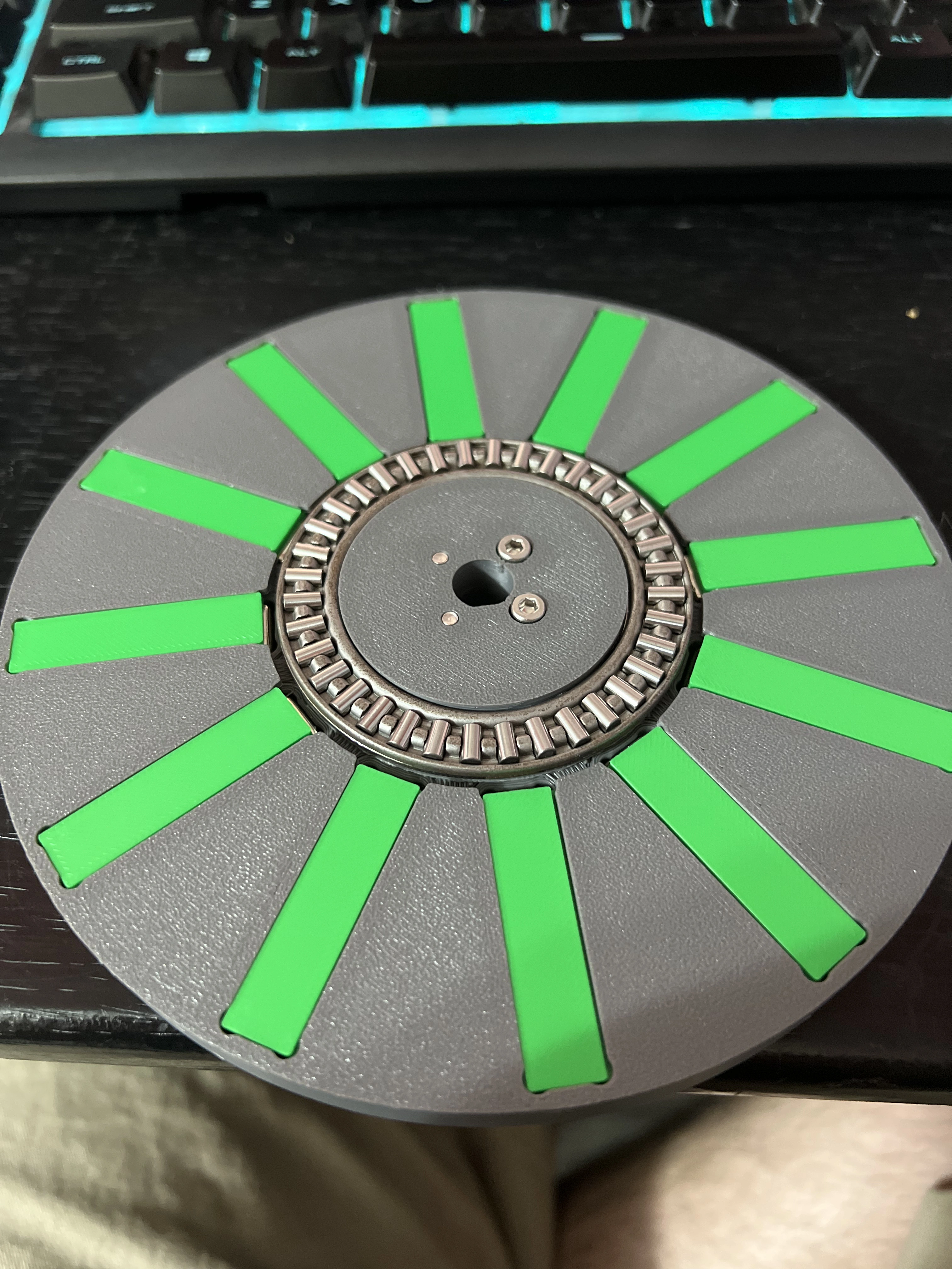
A needle bearing helped maintain the air gap in some areas, but the rotor itself needed to eventually move to metal. The coil holders ideally need to be steel. Both of those problems are still being worked on as I develop the CNC mill side of the equation.
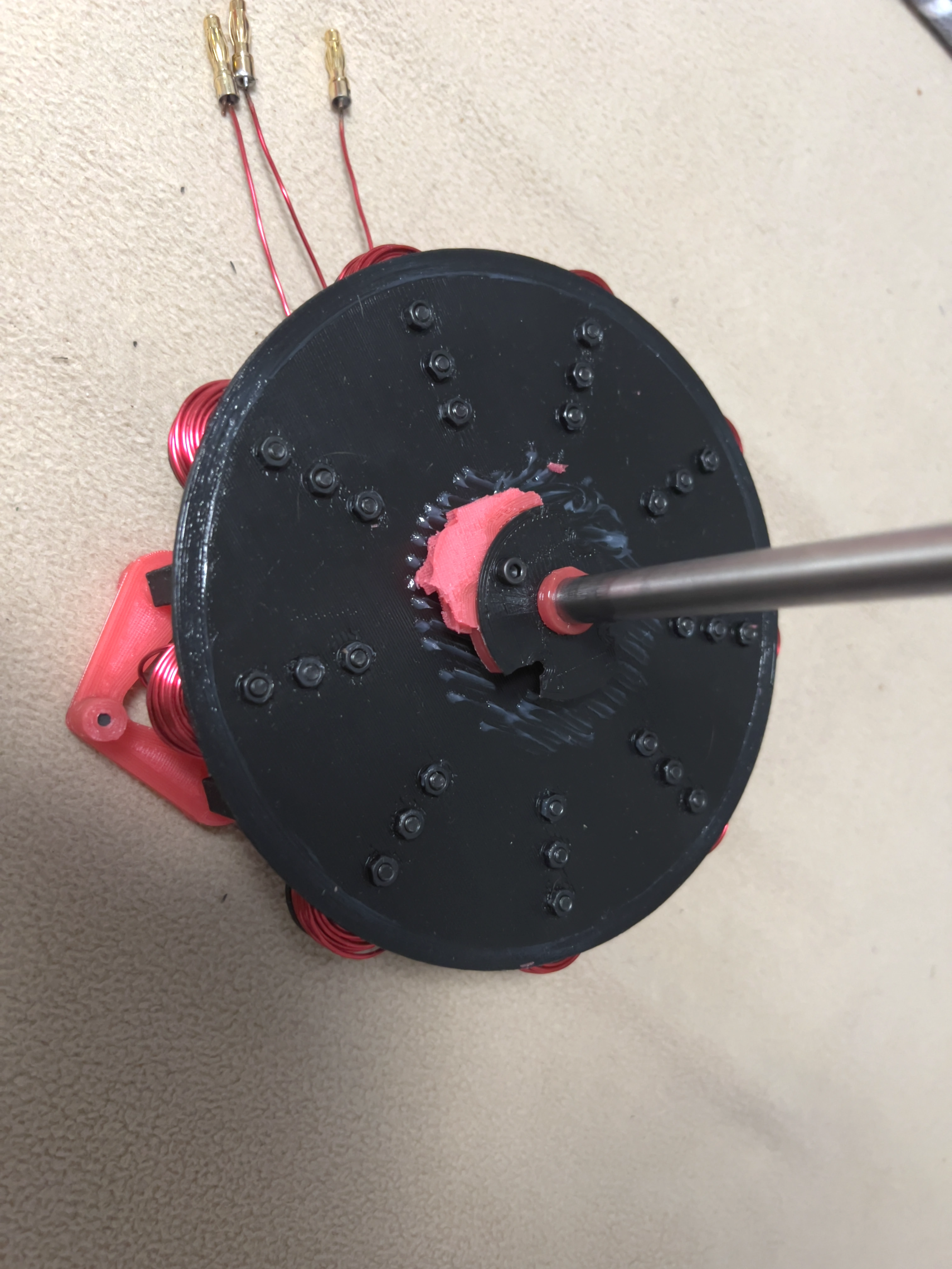
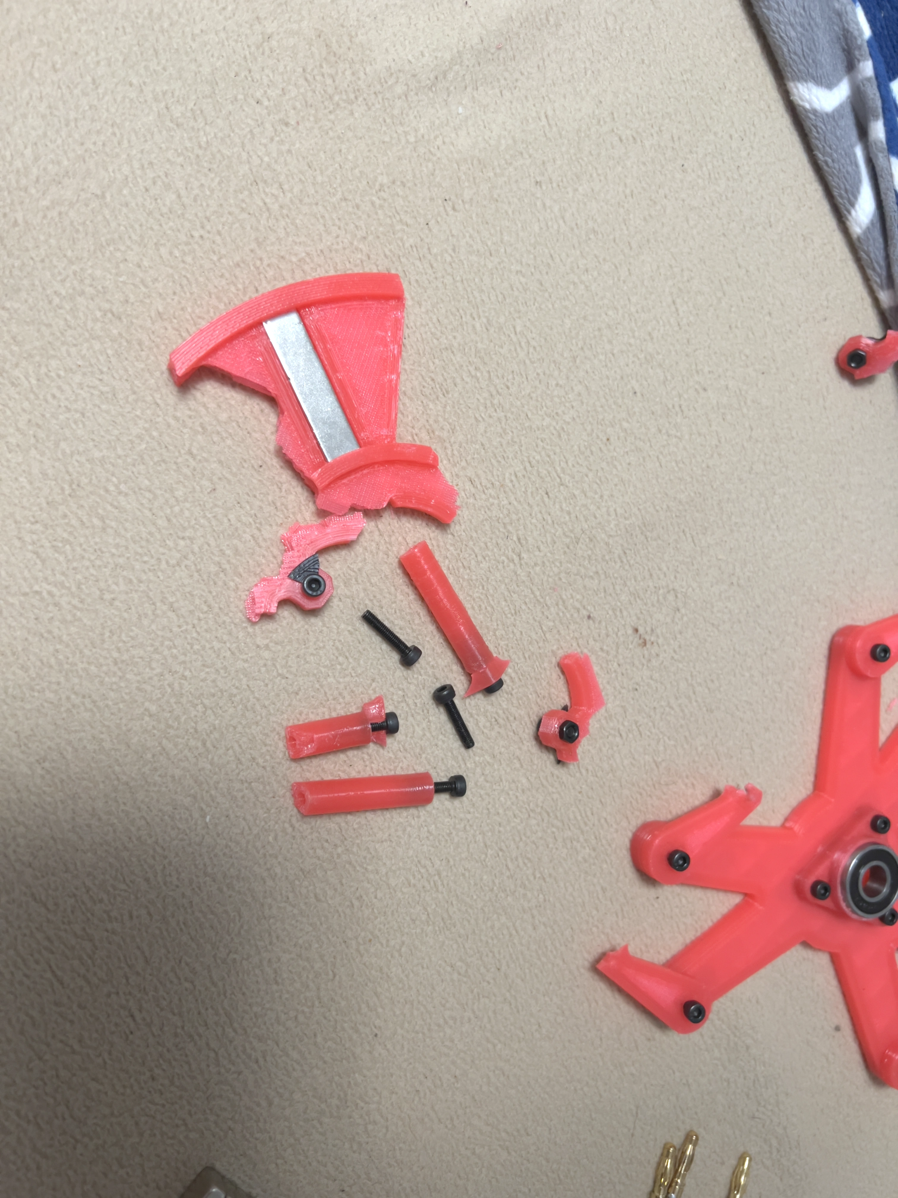
I had to decide early how the various components would eventually be made. Casting from a 3D print (open cast or lost-PLA) was possible, but my earlier casting attempts produced rough surface finishes and parts that were out of dimensional tolerance. I decided machining (milling) was the better long-term path, but I first needed to acquire a mill.
In the meantime I kept the part designs simple enough that they could be both 3D printedand milled later. One early rotor design had pockets that the magnets slid into during the print, after which the print resumed and encapsulated them. That geometry is essentially impossible to machine subtractively. I later redesigned it with a sliding cover piece on both sides. This still retains the magnets securely, allows them to be removed if needed, and is manufacturable by both additive and subtractive processes.
This challenge covers everything else I simply didn't know and had to figure out along the way. How do coils actually work? Do turns matter more than amperage or voltage? What type of bearing should I use?
Early on I used a standard roller bearing. It quickly became a problem because it could not support the axial loads well, leading to seizing and poor load distribution. The physical size of the bearing also forced the motor to be too wide in the center — exactly where the air gap between stator and rotor needs to be as small as possible.
I also wasn't sure how many coils and magnet slots to use, so I simply maximized the magnetic surface area of both the rotor and stator. This seemed intuitive and matched what most other motors do. Cogging forces became an issue — the motor didn't want to rotate. The problem was not simply “too much steel,” but where that steel was. The screws that held the coil holders sat outside the coils, so the magnets pulled on the screws instead of the copper. The coils had to fight that attraction just to turn the rotor. I fixed it by running the screws through the center of the coils, where the steel helps guide magnetic flux toward the magnets instead of competing with the coils.
There are two main axial-flux configurations: an "I" configuration (single stator in the middle with two rotors outside) or an "H" configuration (two stators outside with the rotor in the middle). I had no way of knowing which would be better at the time. Because I knew the copper coils would get hot, I chose the H configuration so the coils would stay exposed for future cooling. This also lowered the rotational inertia of the rotor, which should make it more responsive. The downside is higher copper cost and weight, plus the eventual need for backing iron on the outside of each stator to redirect magnetic flux — something that will require steel and therefore the mill.
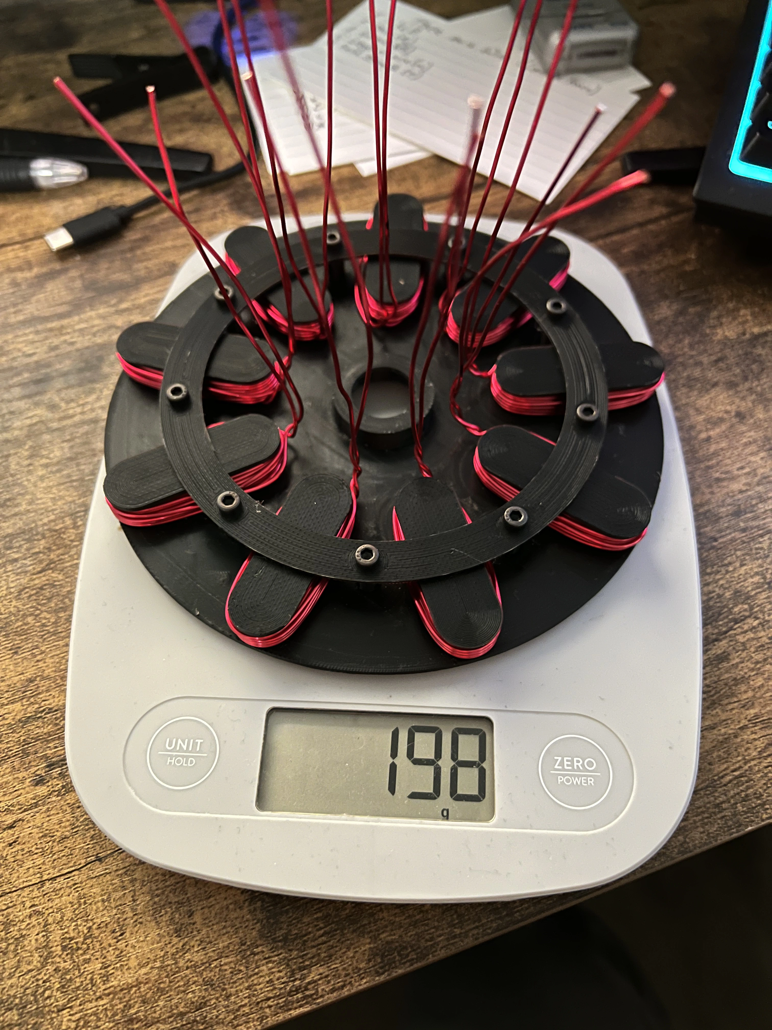
The motor started with 6 coils in an ABC Wye configuration (research at the time suggested this offered better torque) and 8 magnets. From there I scaled in a 3:4 ratio — adding 3 coils and 4 magnets at a time — until I reached 9 coils and 12 magnets and ran out of packaging space on the stator. The rotor still has room for shorter magnets and will likely be doubled to 24 magnets in a future iteration, provided the walls between magnet pockets remain strong enough at high RPM.
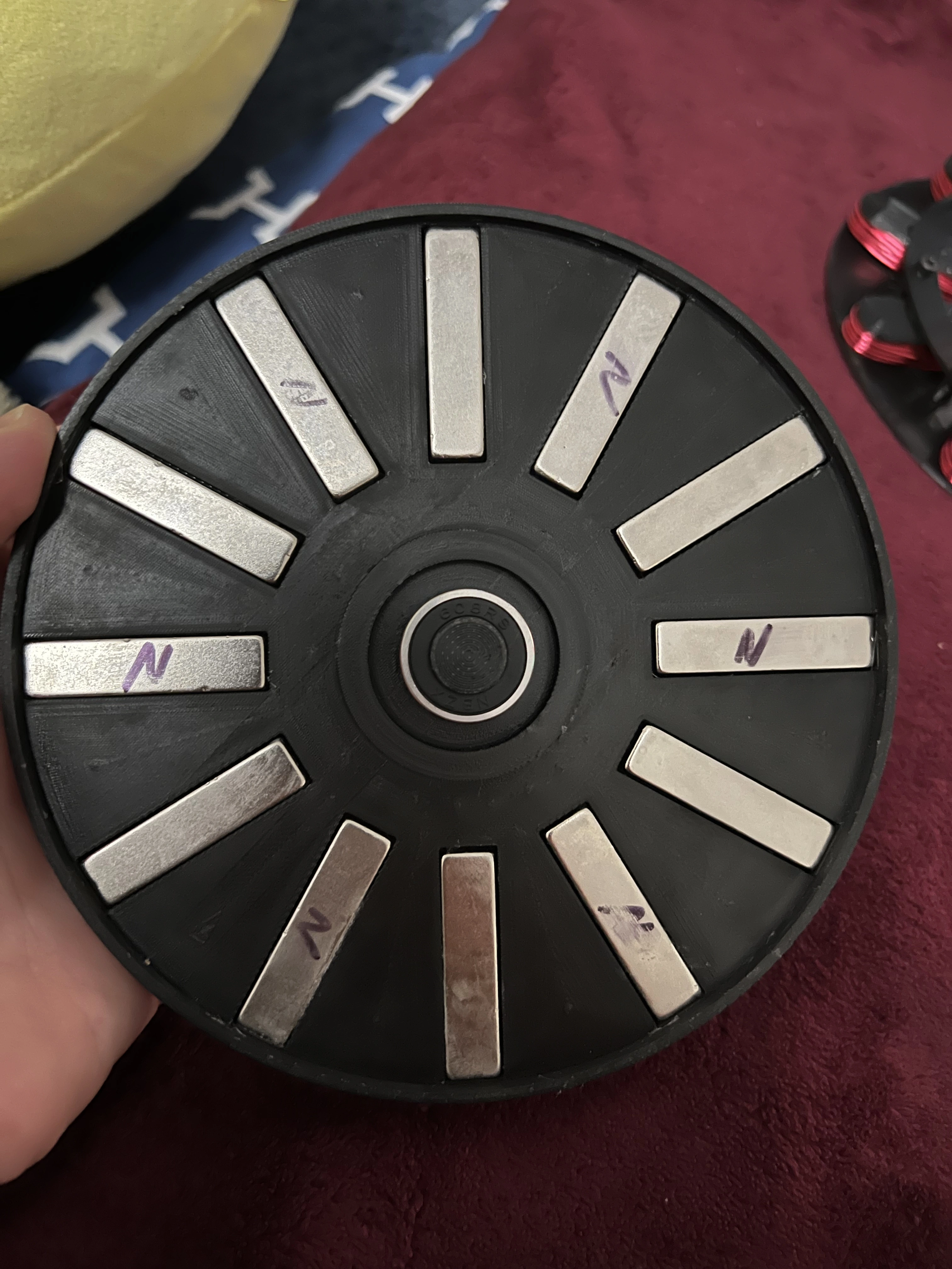
The shaft is a D-profile rod. These are easy to locate and much simpler to print adapters for than a splined shaft. The rotor connects to the shaft through a replaceable adapter. Early versions used a fully 3D-printed shaft, which snapped under load. After switching to a metal rod, the plastic adapter became the weak point — it would spin on the shaft once the motor produced enough torque, and the heat from the shaft would soften the plastic. The adapter was one of the first parts I remade in aluminum once the CNC mill was working, and it has held up since.
Target air gap is 2 mm with the current plastic parts, with the intention of reducing it to ~1 mm once metal components are used (to allow for some flex). Magnetic strength falls off with the inverse square of distance, so maintaining a consistent, small gap is critical. If the rotor wobbles while spinning, the closer side is pulled even closer in a positive feedback loop.
I deliberately used a dual-stator (H) configuration. The stator holds modular coil holders so I can swap different coil sizes during testing. Magnetic steel screws hold the coil holders and run through the center of the coils to help transfer flux toward the magnets. When those same screws were outside the coils, they caused the early cogging problem.
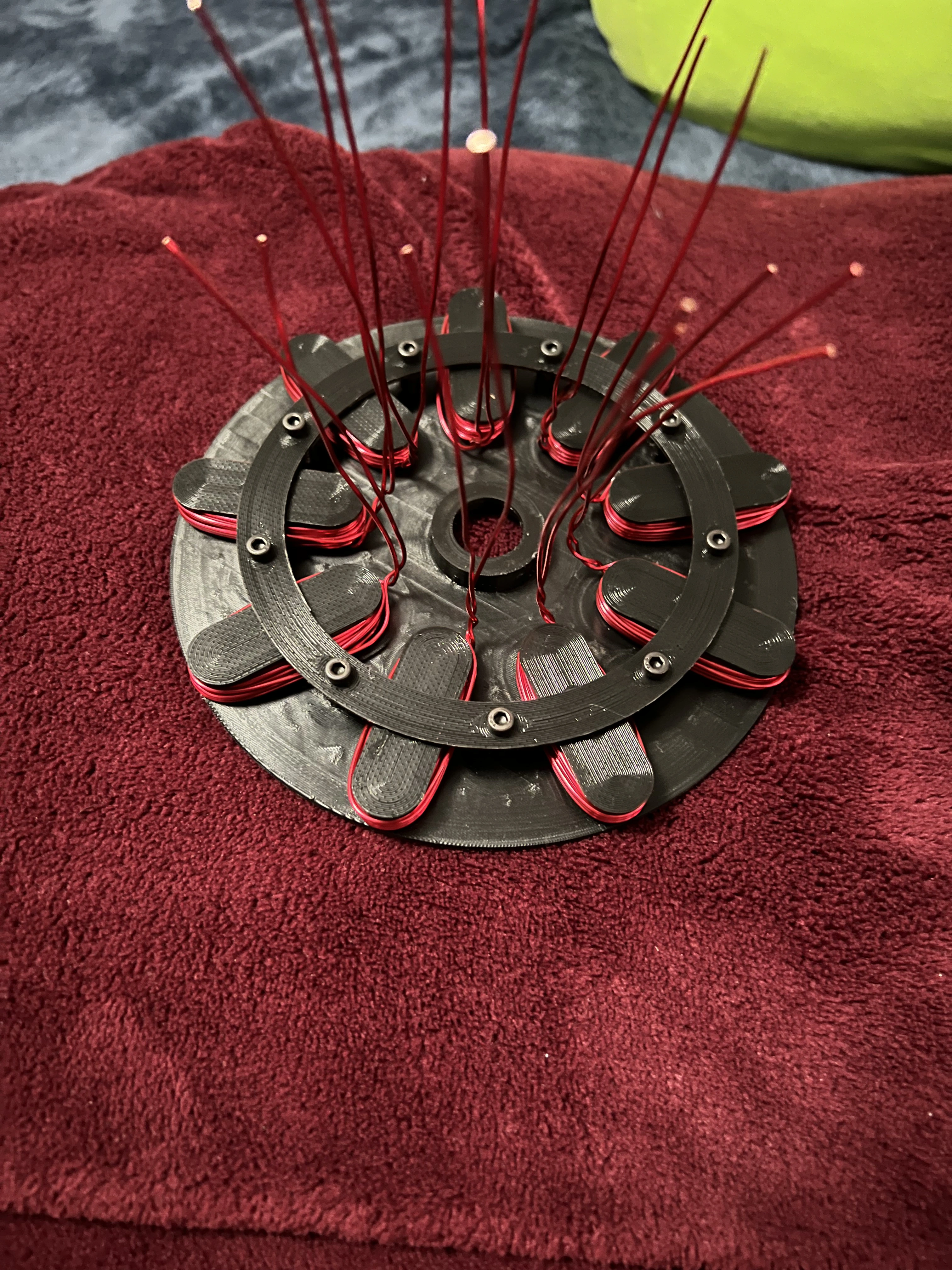
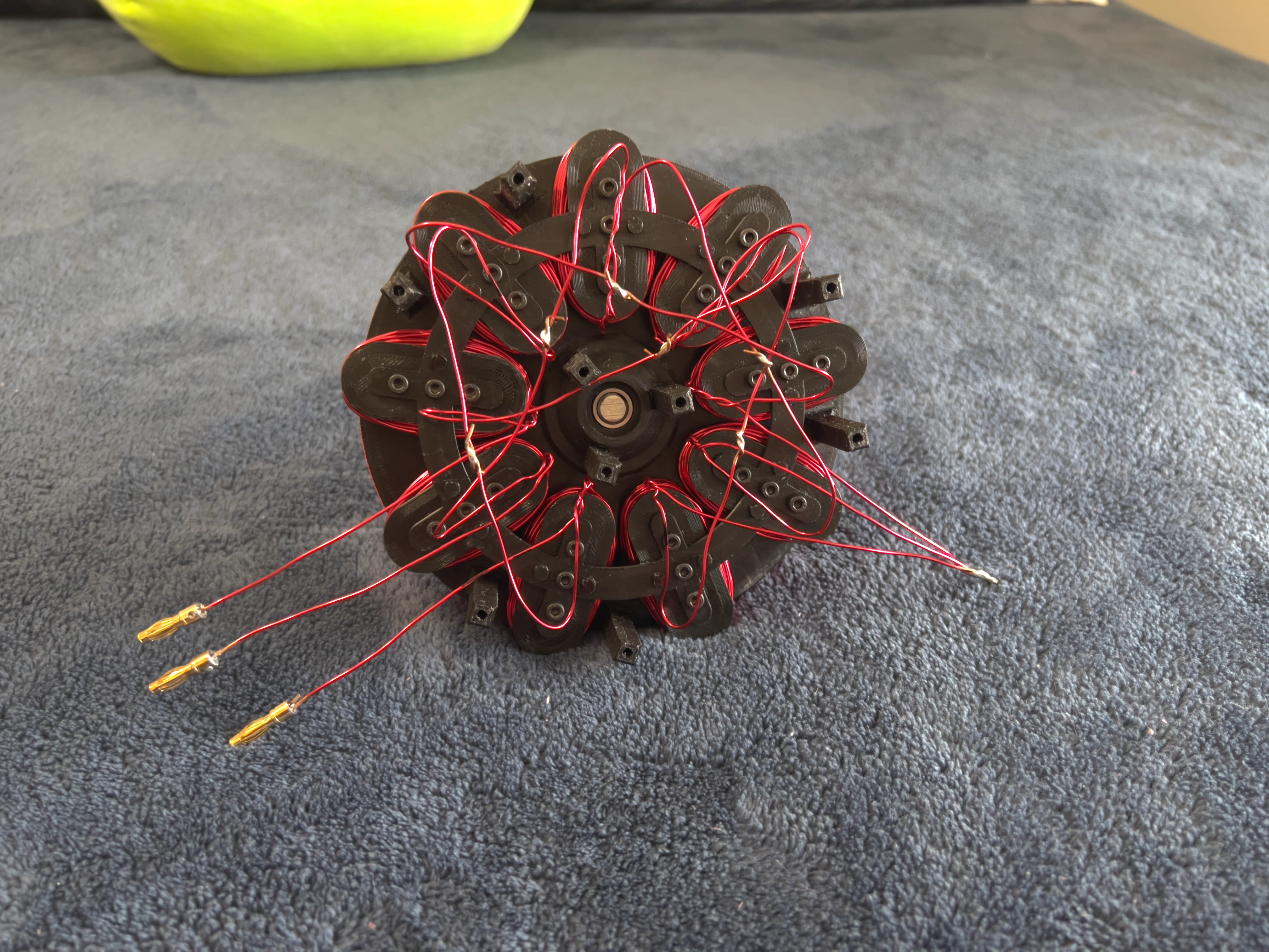
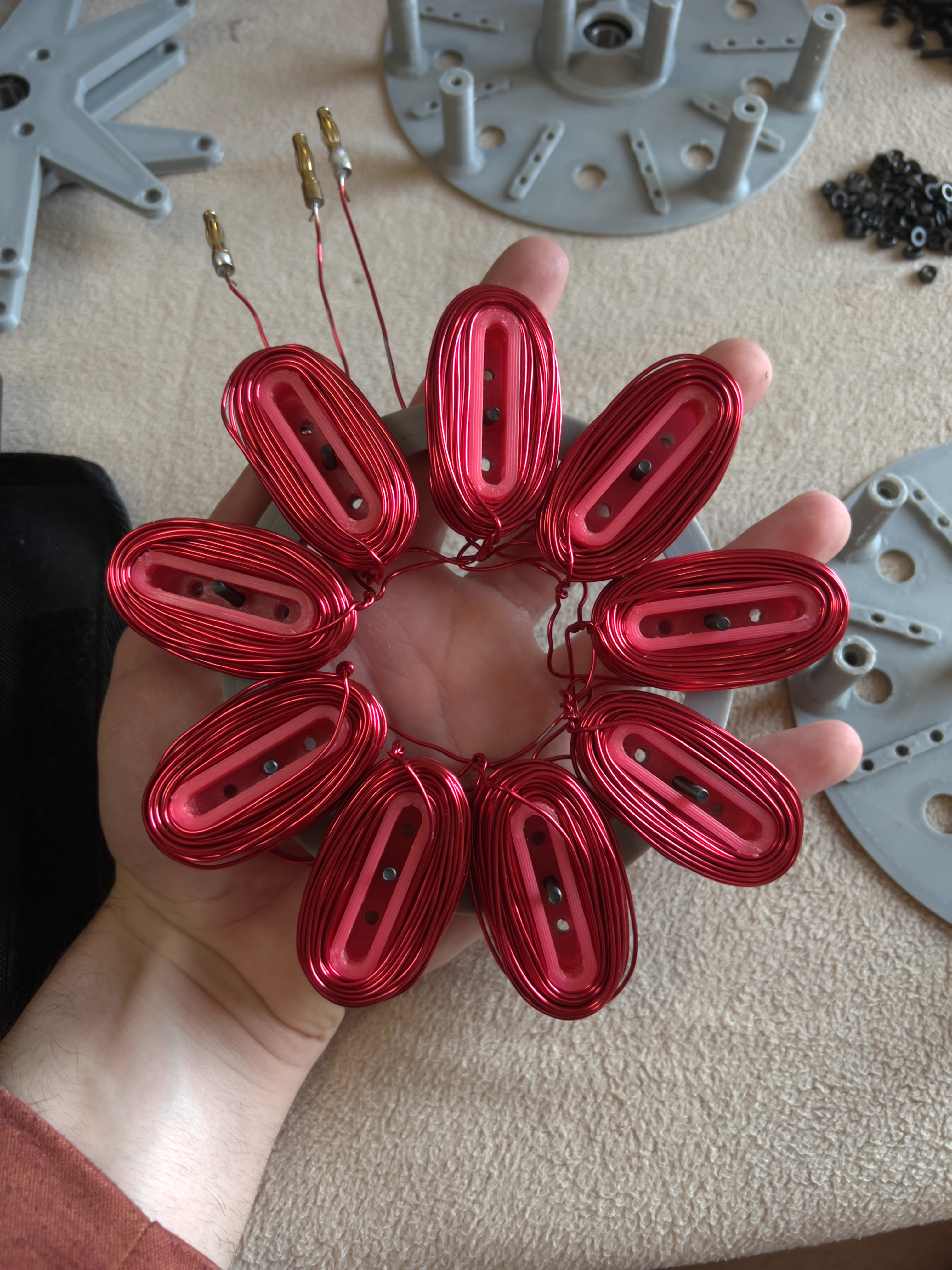
For design 3 I packed every available turn of copper into the holder. More copper means stronger fields for a given current — until heat and cogging force a compromise.
The entire motor was designed in Fusion 360. Early prototypes were printed on an Ender-3 Pro. More recent parts have been printed on a Creality K2+, which offers better accuracy, much faster print times, and support for higher-temperature materials such as PETG and ABS — useful for components like the coil holders that see heat.
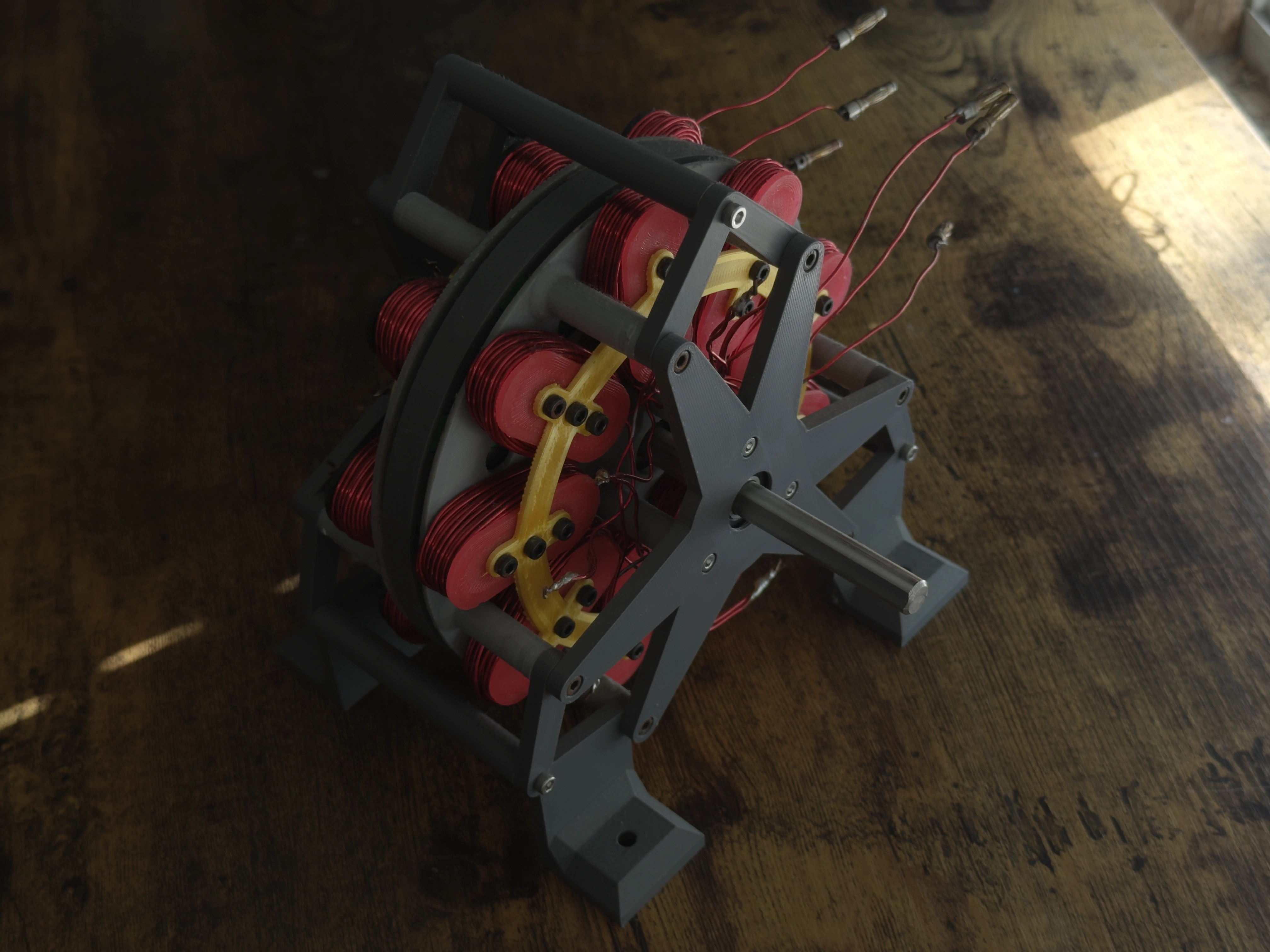
The motor went through several iterations over many weeks. It gradually became more complex and precise as my understanding improved and as I fixed problems that only appeared once the design left the computer.
As of now the motor is functional with 9 coils and 12 magnets. I have roughly estimated peak speed around 2000 RPM. Continuous output is approximately 250 W, with short peaks near 700 W. At those higher power levels the coils get very warm and the plastic rotor begins to lose structural integrity.
The next major hurdle is machining the rotor from aluminum. This should allow higher rotational speeds and help maintain a more consistent air gap (plastic tends to warp, especially when the motor is turned while the rotor is spinning — something that will happen constantly once the motor is mounted on a vehicle). After that, the coil holders need to move to steel, as they are already starting to soften when running more than ~8 A continuously.
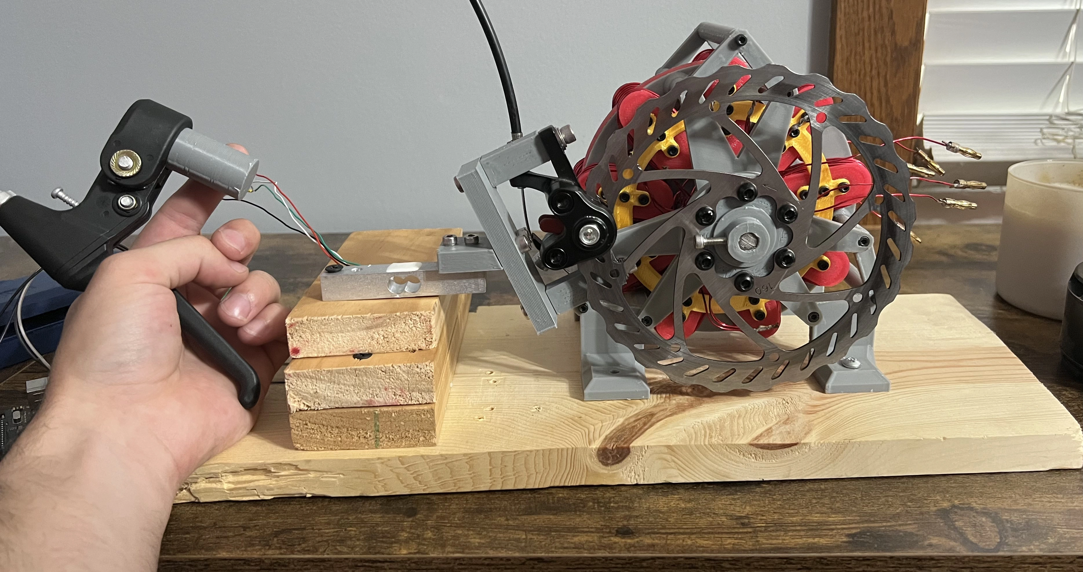
To measure performance I built a simple brake dynamometer using a load cell at a known distance from the axis of rotation. Vibration makes the readings noisy, but it has been good enough to estimate RPM and power. Comparing mechanical output to electrical input from the motor controller shows the current prototype is roughly 30% efficient — not great, but acceptable for these early plastic iterations.